Typical Wiring
745
Transformer Management Relay
Installat
ion
http://www.GEindustrial.com/multilin
3–13
GE Multilin
RS485 / RS422
Communications
The 745 provides the user with two rear communication ports which may be used
simultaneously. Both implement a subset of the AEG Modicon Modbus protocol as
outlined in publication
GEK-106636: 745 Communications Guide
.
The first port, COM1, can be used in the two wire RS485 mode or the four wire
RS422 mode, but will not operate in both modes at the same time. In the RS485
mode, data transmission and reception are accomplished over a single twisted pair
with transmit and receive data alternating over the same two wires. These wires
should be connected to the terminals marked RS485. The RS422 mode uses the
COM1 terminals designated as RS485 for receive lines, and the COM1 terminals
designated as RS422 for transmit lines. The second port, COM2, is intended for the
two wire RS485 mode only. Through the use of these ports, continuous monitoring
and control from a remote computer, SCADA system or PLC is possible.
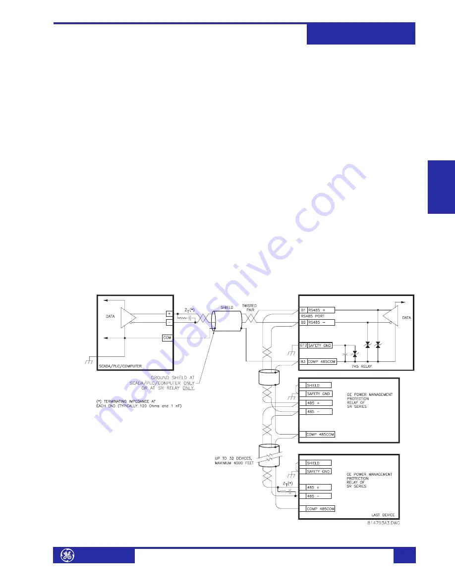
To minimize errors from noise, the use of shielded twisted-pair wire is
recommended. Correct polarity should also be observed. For instance, the relays
must be connected with all B1 terminals (labeled COM1 RS485+) connected
together, and all B2 terminals (labeled COM1 RS485–) connected together. Terminal
B3 (labeled COM1 RS485 COM) should be connected to the common wire inside the
shield. To avoid loop currents, the shield should be grounded at one point only. Each
relay should also be daisy-chained to the next in the link. A maximum of 32 relays
can be connected in this manner without exceeding driver capability. For larger
systems, additional serial channels must be added. It is also possible to use
commercially available repeaters to include more than 32 relays on a single channel.
Star or stub connections should be avoided entirely.
Lightning strikes and ground surge currents can cause large momentary voltage
differences between remote ends of the communication link. For this reason, surge
protection devices are internally provided at both communication ports. An isolated
power supply with an optocoupled data interface also acts to reduce noise coupling.
To ensure maximum reliability, all equipment should have similar transient
protection devices installed.
FIGURE 3–16: RS485 Wiring
Summary of Contents for Multilin 745
Page 2: ......


