3–14
850 FEEDER PROTECTION SYSTEM – INSTRUCTION MANUAL
FRONT CONTROL PANEL INTERFACE
CHAPTER 3: INTERFACES
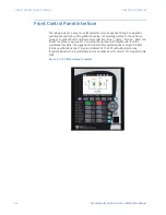
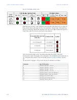
Some status indicators are common while some are feature specific which is dependent
upon the order code. The common status indicators in the first column are described
below.
•
IN SERVICE
This LED indicates that control power is present, all monitored inputs, outputs, and
internal systems are OK, and that the device is programmed.
•
TRIP
This LED indicates that the FlexLogic operand serving as a trip switch has operated.
This indicator always latches so a reset command must be initiated to allow the latch
to be reset.
•
ALARM
This LED indicates that the FlexLogic operand serving as an alarm switch has
operated. Latching of the indicator depends on the selected protection function. The
Reset command must be initiated to allow the latch to be reset.
•
PICKUP
This LED indicates that at least one element is picked up. This indicator is never
latched.
•
TEST MODE
This LED indicates that the relay is in test mode.
•
MESSAGE
This LED indicates the presence of target messages detected by the relay.
•
PHASE A FAULT
This LED indicates that phase A of the Phase Time Overcurrent 1 function has
operated.
•
PHASE B FAULT
This LED indicates that phase B of the Phase Time Overcurrent 1 function has
operated.
•
PHASE C FAULT
This LED indicates that phase C of the Phase Time Overcurrent 1 function has
operated.
•
GROUND FAULT
This LED indicates that the Ground Time Overcurrent 1 function has operated.
•
50P INST OC
This LED indicates that the Phase Instantaneous Overcurrent 1 function has operated.
•
27 PHASE UV (Order Code without Autoreclose)
This LED indicates that the Phase Undervoltage 1 function has operated.
•
LOCKOUT (Order Code with Autoreclose)
This LED indicates that the Autoreclose function has reached the lockout stage.
Summary of Contents for Multilin 850
Page 10: ...VIII 850 FEEDER PROTECTION SYSTEM INSTRUCTION MANUAL ...
Page 135: ...CHAPTER 3 INTERFACES SOFTWARE INTERFACE 850 FEEDER PROTECTION SYSTEM INSTRUCTION MANUAL 3 41 ...
Page 151: ...CHAPTER 3 INTERFACES SOFTWARE INTERFACE 850 FEEDER PROTECTION SYSTEM INSTRUCTION MANUAL 3 57 ...
Page 153: ...CHAPTER 3 INTERFACES SOFTWARE INTERFACE 850 FEEDER PROTECTION SYSTEM INSTRUCTION MANUAL 3 59 ...
Page 439: ...CHAPTER 7 MONITORING FUNCTIONS 850 FEEDER PROTECTION SYSTEM INSTRUCTION MANUAL 7 19 ...
Page 644: ...11 20 850 FEEDER PROTECTION SYSTEM INSTRUCTION MANUAL FLEXELEMENTS CHAPTER 11 METERING ...

