CHAPTER 5: DEVICE, SYSTEM, INPUT AND OUTPUT SETPOINTS
DEVICE
850 FEEDER PROTECTION SYSTEM – INSTRUCTION MANUAL
5–5
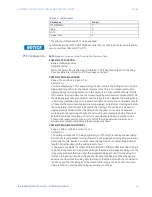
Table 5-1: Time Sources
* The priority of IRIG-B and PTP can be swapped.
FASTPATH:
Synchronization by IEC103, DNP, Modbus and IEC104 is not going to be issued if there is a
sync source from IRIG-B, SNTP or PTP.
PTP Configuration
Path
:
Setpoints > Device > Real Time Clock > Precision Time
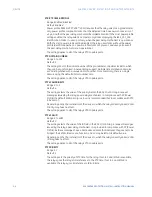
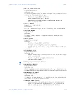
PORT 4(5) PTP FUNCTION
Range: Disabled, Enabled
Default: Enabled
When the port setting is selected as “Disabled,” PTP is disabled on the port. The relay
does not generate, or listen to, PTP messages on the port.
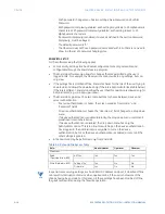
PORT 4(5) PATH DELAY ADDER
Range: 0 to 60000 ns in steps of 1 ns
Default: 0 ns
The time delivered by PTP is advanced by the time value in the setting prior to the time
being used to synchronize the relay’s real time clock. This is to compensate for time
delivery delays not compensated for in the network. In a fully compliant Power Profile
(PP) network, the peer delay and the processing delay mechanisms compensate for all
the delays between the grandmaster and the relay. In such networks, the setting is zero.
In networks containing one or more switches and/or clocks that do not implement both
of these mechanisms, not all delays are compensated, so the time of message arrival at
the relay is later than the time indicated in the message. The setting can be used to
approximately compensate for the delay. Since the relay is not aware of network
switching that dynamically changes the amount of uncompensated delay, there is no
setting that always completely corrects for uncompensated delay. A setting can be
chosen that reduces worst-case error to half of the range between minimum and
maximum uncompensated delay if these values are known.
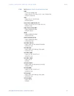
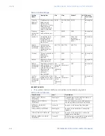
PORT 4(5) PATH DELAY ASYMMETRY
Range: -1000 to +1000 ns in steps of 1 ns
Default: 0 ns
The setting corresponds to “Delay Asymmetry” in PTP, which is used by the peer delay
mechanism to compensate for any difference in the propagation delay between the two
directions of a link. Except in unusual cases, the two fibers are of essentially identical
length and composition, so the setting is set to zero.
In unusual cases where the length of link is different in different directions, the setting is
to be set to the number of nanoseconds longer the Ethernet propagation delay is to the
relay compared with the mean of path propagation delays to and from the relay. For
instance, if it is known say from the physical length of the fibers and the propagation
speed in the fibers that the delay from the relay to the Ethernet switch it is connected to
is 9000 ns and that the delay from the switch to the relay is 11000 ns, then the mean
delay is 10000 ns, and the path delay asymmetry is +1000 ns.
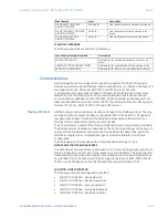
Time Source
Priority
PTP (IEEE1588)
1*
IRIG-B
2*
SNTP
3
Internal Clock
4
Summary of Contents for Multilin 850
Page 10: ...VIII 850 FEEDER PROTECTION SYSTEM INSTRUCTION MANUAL ...
Page 135: ...CHAPTER 3 INTERFACES SOFTWARE INTERFACE 850 FEEDER PROTECTION SYSTEM INSTRUCTION MANUAL 3 41 ...
Page 151: ...CHAPTER 3 INTERFACES SOFTWARE INTERFACE 850 FEEDER PROTECTION SYSTEM INSTRUCTION MANUAL 3 57 ...
Page 153: ...CHAPTER 3 INTERFACES SOFTWARE INTERFACE 850 FEEDER PROTECTION SYSTEM INSTRUCTION MANUAL 3 59 ...
Page 439: ...CHAPTER 7 MONITORING FUNCTIONS 850 FEEDER PROTECTION SYSTEM INSTRUCTION MANUAL 7 19 ...
Page 644: ...11 20 850 FEEDER PROTECTION SYSTEM INSTRUCTION MANUAL FLEXELEMENTS CHAPTER 11 METERING ...


