5–58
850 FEEDER PROTECTION SYSTEM – INSTRUCTION MANUAL
DEVICE
CHAPTER 5: DEVICE, SYSTEM, INPUT AND OUTPUT SETPOINTS
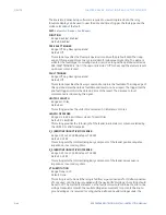
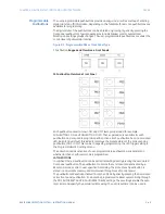
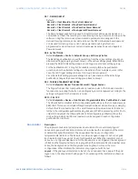
TEXT LINE 1 (2,3)
Range: 15 Alphanumeric Characters
Default: [blank]
These settings specify the displayed text on the corresponding line in the alarm
indicator. Three lines can be displayed with each line allowing up to 15 alphanumeric
characters.
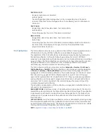
TEXT COLOR
Range: Black, Red, Yellow, Blue, Green, Teal, Purple, White
Default: White
This setting specifies the color of the alarm indicator text.
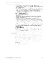
BACK COLOR
Range: Black, Red, Yellow, Blue, Green, Teal, Purple, White
Default: Red
This setting specifies the color of the alarm indicator background. When the indicator
becomes active, the background changes color from the default Black to the
programmed alarm back color.
Tab Pushbuttons
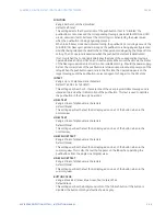
The Tab Pushbuttons provide an easy and error-free method of entering digital state (on,
off) information. Twenty (20) Tab Pushbuttons are available for programming.
The digital state of the Tab Pushbuttons can be entered locally (by directly pressing the
front panel pushbutton) or through Modbus by specifying the correct COMMAND
sequence. Typical applications include breaker control, autorecloser blocking, and settings
groups changes. The Tab Pushbuttons are under the control level of password protection.
Only one pushbutton can be pressed at a time. If multiple pushbuttons are pressed
simultaneously, the button pressed first takes the priority.
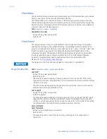
The Tab Pushbutton settings can be accessed from
Setpoints > Device > Front Panel >
Tab Pushbuttons > Tab PB1
. The Tab Pushbutton control can be executed by navigating
to
Status > Summary > Tab Pushbuttons
. By default, the summary page is shown to
quickly glance at the active tab pushbuttons. The individual pages can then be accessed
from the summary page.Each Tab Pushbutton asserts its own OFF and ON FlexLogic
operands (for example, TAB PB 1 ON and TAB PB 1 OFF). These operands are available for
each pushbutton and can be used to program specific actions. Each pushbutton has an
associated “LED” indicator. By default, this indicator displays the present status of the
corresponding pushbutton ON state.
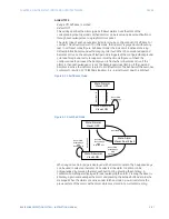
The activation and deactivation of Tab Pushbuttons is dependent on whether latched or
self-reset mode is programmed.
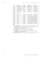
SELF-RESET MODE:
In Self-reset mode, a Tab Pushbutton remains active for the time it is
pressed (the pulse duration) plus the Dropout time specified in the settings. The pushbutton
is deactivated in Self-reset mode when the dropout delay specified in the Dropout Time
setting expires. The pulse duration of the pushbutton must be at least 100ms to operate
the pushbutton.
LATCHED MODE:
In Latched Mode, a pushbutton can be set (activated) by directly pressing
the associated tab pushbutton. The pushbutton maintains the set state until deactivated
by another press of the same button. The state of each pushbutton is stored in non-volatile
memory and maintained through the loss of control power.
Path
:
Setpoints > Device > Front Panel > Tab PBs > Tab PB1(X)
Summary of Contents for Multilin 850
Page 10: ...VIII 850 FEEDER PROTECTION SYSTEM INSTRUCTION MANUAL ...
Page 135: ...CHAPTER 3 INTERFACES SOFTWARE INTERFACE 850 FEEDER PROTECTION SYSTEM INSTRUCTION MANUAL 3 41 ...
Page 151: ...CHAPTER 3 INTERFACES SOFTWARE INTERFACE 850 FEEDER PROTECTION SYSTEM INSTRUCTION MANUAL 3 57 ...
Page 153: ...CHAPTER 3 INTERFACES SOFTWARE INTERFACE 850 FEEDER PROTECTION SYSTEM INSTRUCTION MANUAL 3 59 ...
Page 439: ...CHAPTER 7 MONITORING FUNCTIONS 850 FEEDER PROTECTION SYSTEM INSTRUCTION MANUAL 7 19 ...
Page 644: ...11 20 850 FEEDER PROTECTION SYSTEM INSTRUCTION MANUAL FLEXELEMENTS CHAPTER 11 METERING ...

