5–64
850 FEEDER PROTECTION SYSTEM – INSTRUCTION MANUAL
DEVICE
CHAPTER 5: DEVICE, SYSTEM, INPUT AND OUTPUT SETPOINTS
Installation
Path:
Setpoints > Device > Installation
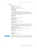
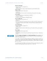
DEVICE NAME
Range: Up to 13 alphanumeric characters
An alphanumeric name may be assigned to the device.
DEVICE IN SERVICE
Default: Not Ready
Range: Not Ready, Ready
The relay is defaulted to the “Not Ready” state when it leaves the factory. This
safeguards against the installation of a relay whose settings have not been entered.
When powered up successfully, the “IN SERVICE” LED becomes red. The relay in the “Not
Ready” state blocks signaling of any output relay. These conditions remain until the
relay is explicitly put in the “Ready” state.
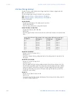
SERVICE COMMAND
Range: 0 to 65535
Default: 0
See
Password Recovery Procedure
for details.
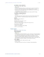
TEMPERATURE DISPLAY
Range: Celsius, Fahrenheit
Default: Celsius
Selects engineering unit of temperature display.
VALIDATE CANBUS IO
Range: NO, YES
When the relay is booted the 8 Series relay enumerates the installed IO cards
automatically. When the relay is commissioned and the Validate CANBUS IO command
is set to Yes the current auto detect value is saved to non-volatile memory. This value is
then used to configure all display dependencies and used in self-test validation.
REMOTE IO DETECT VALUE
Range: Up to 6 alphanumeric characters
Shows the letter type of the Remote RTD card Board ID installed (e.g. GGGG).
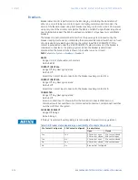
CURRENT CUTOFF
Range: 0.000 to 1.000 p.u. in steps of 0.001 p.u.
Default: 0.020 p.u.
VOLTAGE CUTOFF
Range: 0.0 to 300.0 in steps of 0.1 V
Default: 1.0 V
FASTPATH:
Lower the Voltage Cutoff and Current Cutoff levels with care as the relay accepts lower
signals as valid measurements. Unless dictated otherwise by a specific application, the
default settings of “0.020 pu” for current and “1.0 V” for voltage are recommended.”
Summary of Contents for Multilin 850
Page 10: ...VIII 850 FEEDER PROTECTION SYSTEM INSTRUCTION MANUAL ...
Page 135: ...CHAPTER 3 INTERFACES SOFTWARE INTERFACE 850 FEEDER PROTECTION SYSTEM INSTRUCTION MANUAL 3 41 ...
Page 151: ...CHAPTER 3 INTERFACES SOFTWARE INTERFACE 850 FEEDER PROTECTION SYSTEM INSTRUCTION MANUAL 3 57 ...
Page 153: ...CHAPTER 3 INTERFACES SOFTWARE INTERFACE 850 FEEDER PROTECTION SYSTEM INSTRUCTION MANUAL 3 59 ...
Page 439: ...CHAPTER 7 MONITORING FUNCTIONS 850 FEEDER PROTECTION SYSTEM INSTRUCTION MANUAL 7 19 ...
Page 644: ...11 20 850 FEEDER PROTECTION SYSTEM INSTRUCTION MANUAL FLEXELEMENTS CHAPTER 11 METERING ...

