6–12
850 FEEDER PROTECTION SYSTEM – INSTRUCTION MANUAL
CURRENT ELEMENTS
CHAPTER 6: PROTECTION SETPOINTS
PICKUP
Range: 0.050 to 30.000 x CT in steps of 0.001 x CT
Default: 1.000 x CT
CURVE
Range: IEEE Extremely / Very / Moderately Inverse; ANSI Extremely / Very / Normally /
Moderately Inverse; Definite time IEC A / B / C and Short Inverse; IAC Extremely / Very /
Inverse / Short Inverse; FlexCurve A / B / C / D, I2t, I4t
Default: IEEE Moderately Inverse
TDM
Range: 0.05 to 600.00 in steps of 0.01
Default: 1.00
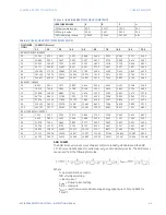
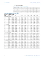
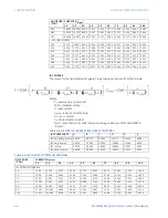
The setting provides a selection for Time Dial Multiplier which modifies the operating
times per the selected inverse curve. For example, if an IEEE Extremely Inverse curve is
selected with TDM = 2, and the fault current is 5 times bigger than the PKP level, the
operation of the element will not occur before 2.59 s have elapsed after Pickup.
RESET
Range: Instantaneous, Timed
Default: Instantaneous
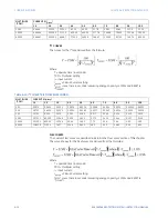
Selection of an Instantaneous or a Timed reset time is provided using this setting. If
Instantaneous reset is selected, the Phase TOC element will reset instantaneously
providing the current drops below 97-98% of the Phase TOC PKP level. If Timed reset is
selected, the time to reset is calculated based on the reset equation for the selected
inverse curve.
DIRECTION
Range: Disabled, Forward (Ph Dir OC [1-4] FWD), Reverse (Ph Dir OC [1-4] REV)
Default: Disabled
VOLTAGE RESTRAINT
Range: Disabled, Enabled
Default: Disabled
This setting enables or disables the Voltage Restraint function for the TOC element.
When set to “Enabled” this feature lowers the Pickup value of each individual Phase Time
Overcurrent element in a fixed relationship with its corresponding phase input voltage.
If cold load pickup, autoreclosing, or manual close blocking features are controlling the
protection, the Phase TOC Voltage Restraint does not work, even if “Enabled” is selected.
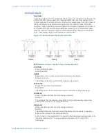
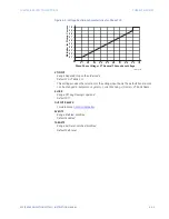
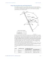
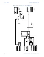
Voltage restraint is used to lower the current pickup level for TOC function in linear
proportion as shown in figure below. For example, if phase TOC PICKUP setting is set to
1.000 XCT, in case of system faults cause generator terminal voltage drops to 0.4 pu
(ratio of Phase-Phase Voltage/ VT Nominal Phase-phase voltage), the new pickup with
voltage restraint would be 1.000*0.4=0.400 xCT. During the fault condition when the
voltage drops, the overcurrent relay pickup also drops linearly and it should be verified
that for the limiting case the new voltage restraint relay pickup should be lower than
(around 50% of) the fault current. Refer IEEE C37.102-2006, Annex-A for more details.
Summary of Contents for Multilin 850
Page 10: ...VIII 850 FEEDER PROTECTION SYSTEM INSTRUCTION MANUAL ...
Page 135: ...CHAPTER 3 INTERFACES SOFTWARE INTERFACE 850 FEEDER PROTECTION SYSTEM INSTRUCTION MANUAL 3 41 ...
Page 151: ...CHAPTER 3 INTERFACES SOFTWARE INTERFACE 850 FEEDER PROTECTION SYSTEM INSTRUCTION MANUAL 3 57 ...
Page 153: ...CHAPTER 3 INTERFACES SOFTWARE INTERFACE 850 FEEDER PROTECTION SYSTEM INSTRUCTION MANUAL 3 59 ...
Page 439: ...CHAPTER 7 MONITORING FUNCTIONS 850 FEEDER PROTECTION SYSTEM INSTRUCTION MANUAL 7 19 ...
Page 644: ...11 20 850 FEEDER PROTECTION SYSTEM INSTRUCTION MANUAL FLEXELEMENTS CHAPTER 11 METERING ...


