CHAPTER 6: PROTECTION SETPOINTS
CURRENT ELEMENTS
850 FEEDER PROTECTION SYSTEM – INSTRUCTION MANUAL
6–53
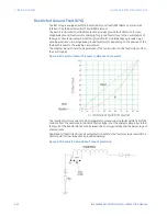
850 implementation of the Restricted Ground Fault protection is a low impedance current
differential scheme. The 850 calculates the magnitude of the ground differential current as
an absolute value from the vector summation of the computed residual current, and the
measured ground current, and applies a restraining current defined as the maximum
measured line current (Imax) to produce a percent slope value. The slope setting allows
determination of the sensitivity of the element based on the class and quality of the CTs
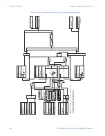
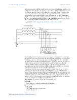
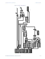
used.The figure below shows typical wiring between the winding and ground CTs and the
850 CT terminals, to assure correct performance of the protection.
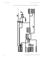
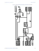
Figure 6-21: Three CT wiring for the Restricted Ground Fault protection
The 850 RGF protection includes ground current supervision mechanism to provide more
security during external non-ground faults associated with CT saturation, that may result
into spurious neutral current, and may jeopardize the security of the RGF 1 protection.
When the GROUND CURRENT SUPERVISION setting is selected as “Enabled”, the algorithm
checks if the ground current measured by the relay satisfies the selected GROUND
CURRENT SUPERV LEVEL, before making operation decision. The ground current
supervision is not active if the GROUND CURRENT SUPERVISION is selected as “Disabled”.
The RGF 1 protection works without the supervision as well.
The settings of this function are applied to the ground and all three phase currents to
produce pickup and trip flags. The RGF 1 pickup flag is asserted, when the restrained
ground differential current is above the PKP value. The RGF 1 operate flag is asserted if the
element stays picked up for the time defined in RGF 1 PKP DELAY. The element drops from
Pickup without operation, if the calculated restrained ground differential current drops
below 97-98% of the Pickup value, before the time for operation is reached.The Restricted
Ground Fault function can be inhibited by a blocking input.
Path
:
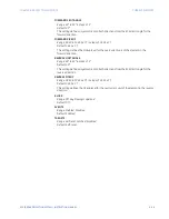
Setpoints > Protection > Group 1(6) > Current > RGF 1 (X)
FUNCTION
Range: Disabled, Trip, Alarm, Latched Alarm, Configurable
Default: Disabled
SIGNAL INPUT
Range: dependant upon the order code
Default: CT Bank 1 -J1
Summary of Contents for Multilin 850
Page 10: ...VIII 850 FEEDER PROTECTION SYSTEM INSTRUCTION MANUAL ...
Page 135: ...CHAPTER 3 INTERFACES SOFTWARE INTERFACE 850 FEEDER PROTECTION SYSTEM INSTRUCTION MANUAL 3 41 ...
Page 151: ...CHAPTER 3 INTERFACES SOFTWARE INTERFACE 850 FEEDER PROTECTION SYSTEM INSTRUCTION MANUAL 3 57 ...
Page 153: ...CHAPTER 3 INTERFACES SOFTWARE INTERFACE 850 FEEDER PROTECTION SYSTEM INSTRUCTION MANUAL 3 59 ...
Page 439: ...CHAPTER 7 MONITORING FUNCTIONS 850 FEEDER PROTECTION SYSTEM INSTRUCTION MANUAL 7 19 ...
Page 644: ...11 20 850 FEEDER PROTECTION SYSTEM INSTRUCTION MANUAL FLEXELEMENTS CHAPTER 11 METERING ...

