6–70
850 FEEDER PROTECTION SYSTEM – INSTRUCTION MANUAL
CURRENT ELEMENTS
CHAPTER 6: PROTECTION SETPOINTS
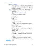
Broken Conductor
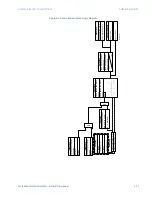
The Broken Conductor detection function detects a line broken conductor condition or a
single-pole breaker malfunction condition through checking the phase current input
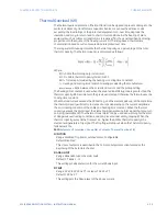
phasors and the I_2 / I_1 ratio. In normal and balanced load situations this ratio is zero,
while in severe load fault conditions an unbalance is produced and this ratio increases. The
intention of this function is to detect a single-phase broken conductor only. As such two-
phase or three-phase broken conductors cannot be detected.
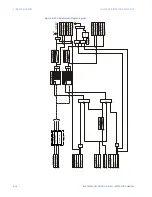
To distinguish between single-phase disappearance and system disturbance in all three
phases (such as load change, switching, etc.), the broken conductor element monitors the
change in all three phase currents at the present instance and at four cycles previous. It
also monitors changes in the I_2 / I_1 ratio, I_1 minimum, and I_1 maximum.
The broken conductor function is not to be used to respond to fault transients and single-
pole tripping/reclosing conditions. The time delay is programmed to a sufficient length to
ensure coordination with the breaker dead time of the recloser function.
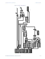
The broken conductor Pickup flag is asserted, when the I_2 / I_1 ratio of the current bank is
above the PKP value, the positive current is in a range of nominal, and phase current
changes. The broken conductor Trip flag is asserted if the element stays picked up for the
time defined by the Pickup time delay. The element instantaneously drops from Pickup
without operation, if the I_2 / I_1 ratio decreases to 97% to 98% of the Pickup value, before
the time for operation is reached.
Path
:
Setpoints > Protection > Group 1(6) > Current > Broken Conductor 1(X)
FUNCTION
Range: Disabled, Trip, Alarm, Latched Alarm, Configurable
Default: Disabled
SIGNAL INPUT
Range: dependant upon the order code
Default: CT Bank 1 -J1
This setting provides the selection for the current bank input.
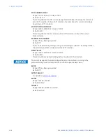
I_2/I_1 RATIO
Range: 20.0% to 100.0% in steps of 0.1%
Default: 20.0%
The setting specifies the ratio of negative-sequence current to positive-sequence
current. When one phase conductor is broken, the I_2 / I_1 ratio with balanced
remaining two phases is 50%. So normally the setting should be set below 50% (for
example, to 30%).
I_1 MIN
Range: 0.05 to 1.00 x CT in steps of 0.01 x CT
Default: 0.10 x CT
The setting specifies the minimum positive-sequence current supervision level. Ensure
the setting is programmed to a level sufficient to prevent I_2 / I_1 from erratic pickup
due to a low I_1 signal. However, the setting is not to be set too high since the broken
conductor condition cannot be detected under light load conditions when I_1 is less
than the value specified by this setting.
I_1 MAX
Range: 0.05 to 5.00 x CT in steps of 0.01 x CT
Default: 1.50 x CT
The setting specifies the maximum I_1 level allowed for the broken conductor function
to operate. When I_1 exceeds this setting, it is considered a fault. This broken conductor
function should not respond to any fault conditions so normally the setting is
programmed to less than the maximum load current.
Summary of Contents for Multilin 850
Page 10: ...VIII 850 FEEDER PROTECTION SYSTEM INSTRUCTION MANUAL ...
Page 135: ...CHAPTER 3 INTERFACES SOFTWARE INTERFACE 850 FEEDER PROTECTION SYSTEM INSTRUCTION MANUAL 3 41 ...
Page 151: ...CHAPTER 3 INTERFACES SOFTWARE INTERFACE 850 FEEDER PROTECTION SYSTEM INSTRUCTION MANUAL 3 57 ...
Page 153: ...CHAPTER 3 INTERFACES SOFTWARE INTERFACE 850 FEEDER PROTECTION SYSTEM INSTRUCTION MANUAL 3 59 ...
Page 439: ...CHAPTER 7 MONITORING FUNCTIONS 850 FEEDER PROTECTION SYSTEM INSTRUCTION MANUAL 7 19 ...
Page 644: ...11 20 850 FEEDER PROTECTION SYSTEM INSTRUCTION MANUAL FLEXELEMENTS CHAPTER 11 METERING ...


