CHAPTER 1: INTRODUCTION
SPECIFICATIONS
850 FEEDER PROTECTION SYSTEM – INSTRUCTION MANUAL
1–25
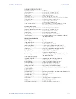
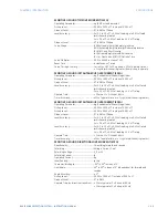
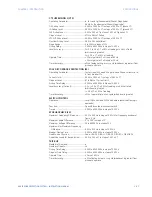
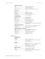
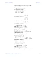
UNDERFREQUENCY (81U)
Pickup Level:..........................................................20.00 to 65.00 Hz in steps of 0.01
Dropout Level: ...................................................... 0.03 Hz
Pickup Time Delay:.............................................0.000 to 6000.000 s in steps of 0.001s
Dropout Time Delay: .........................................0.000 to 6000.000 s in steps of 0.001s
Minimum Operating Voltage: ........................0.000 to 1.250 x VT in steps of 0.001 x VT
Minimum Operating Current: ........................0.000 to 30.000 x CT in steps of 0.001 x CT
Level Accuracy:....................................................± 0.001 Hz
Timer Accuracy: ..................................................± 3% of delay setting or ± ¼ cycle (whichever is greater)
from pickup to operate
Operate Time:.......................................................typically 7.5 cycles at 0.1 Hz/s change
typically 7 cycles at 0.3 Hz/s change
typically 6.5 cycles at 0.5 Hz/s change
FASTPATH:
Typical times are average Operate Times including variables such as frequency change
instance, test method, etc., and may vary by ± 0.5 cycles.
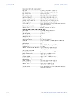
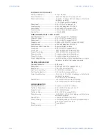
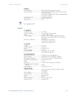
UV REACTIVE POWER (27Q)
Protection Function
Voltages:..................................................................Phasor only
Pickup Voltage:.....................................................0.00 to 1.50 x VT in steps of 0.01
Pickup Vars: ...........................................................1 to 65000 Kvar in steps of 1 Kvar
Dropout Level: ......................................................103% of pickup for Undervoltage
97% of pickup for Over Reactive Power
103% of pickup for Under Reactive Power
Level Accuracy:....................................................±0.5% of reading or ±2V (secondary), whichever is greater
Pickup Time Delay:.............................................0.000 to 600.000 s in steps of 0.001
Timer Accuracy: ..................................................±3% of the delay setting time or ±½ cycle (whichever is
greater) from pickup to operate
Current Supervision Level:..............................0.00 to 0.20 x CT in steps of 0.01
Stages:......................................................................Trip, Alarm and Configurable
Restoration Function
Min Voltage:...........................................................0.05 to 1.50 x VT in steps of 0.01
Min/Max Frequency:..........................................20.00 to 65.00 Hz in steps of 0.01
Restore Time Delay: ..........................................0.00 to 6000.00 s in steps of 0.01
Stages:......................................................................Close and Configurable
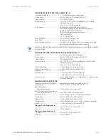
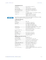
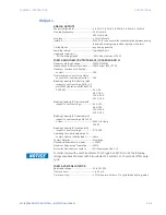
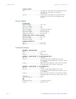
WATTMETRIC GROUND FAULT (32N)
Measured Power: ................................................zero-sequence
Characteristic Angle:.........................................0
º
to 359
º
in steps of 1°
Power Pickup Range:.........................................0.001 to 1.200 CT x VT in steps of 0.001
Pickup Level Accuracy: ....................................± 1% or ± 0.0025 CT x VT, whichever is greater
Hysteresis:..............................................................3% or 0.001 CT x VT, whichever is greater
Curve: .......................................................................Definite Time, Inverse Time, or FlexCurve
Operating Voltage Pickup Level: ..................0.02 to 3.00 x VT in steps of 0.01 x VT
Operating Current Pickup Level: ..................0.002 to 30.000 x CT in steps of 0.001 x CT
Power Pickup Delay:..........................................0.000 to 6000.000 s in steps of 0.001 s
Inverse Time Multiplier:....................................0.01 to 2.00 s in steps of 0.01 s
Operate Time:.......................................................< 40 ms at 1.1 x pickup at 60 Hz,
< 47 ms at 1.1 x pickup at 50 Hz
Curve Timing Accuracy: ..................................± 3% of curve delay or ± ¾ cycle (whichever is greater) from
pickup to operate
Summary of Contents for Multilin 850
Page 10: ...VIII 850 FEEDER PROTECTION SYSTEM INSTRUCTION MANUAL ...
Page 135: ...CHAPTER 3 INTERFACES SOFTWARE INTERFACE 850 FEEDER PROTECTION SYSTEM INSTRUCTION MANUAL 3 41 ...
Page 151: ...CHAPTER 3 INTERFACES SOFTWARE INTERFACE 850 FEEDER PROTECTION SYSTEM INSTRUCTION MANUAL 3 57 ...
Page 153: ...CHAPTER 3 INTERFACES SOFTWARE INTERFACE 850 FEEDER PROTECTION SYSTEM INSTRUCTION MANUAL 3 59 ...
Page 439: ...CHAPTER 7 MONITORING FUNCTIONS 850 FEEDER PROTECTION SYSTEM INSTRUCTION MANUAL 7 19 ...
Page 644: ...11 20 850 FEEDER PROTECTION SYSTEM INSTRUCTION MANUAL FLEXELEMENTS CHAPTER 11 METERING ...

