6–90
850 FEEDER PROTECTION SYSTEM – INSTRUCTION MANUAL
VOLTAGE ELEMENTS
CHAPTER 6: PROTECTION SETPOINTS
TIME FOR VOLTAGE DROPS
Range: 0.000 to 600000.000 s in steps of 0.001 s
Default: 2.000 s
This setting indicates the total time window for which a set number of voltage drops are
allowed before the element issues a time-independent undervoltage trip. If the number
of transient voltage drops exceeds the defined setting within the time defined for the
voltage drops, a time-independent undervoltage trip is issued. This is not a sliding time
window; the time window jumps from one set of time to the next.
FASTPATH:
This setting is only functional if the Counter Mode setting is set to Enabled.
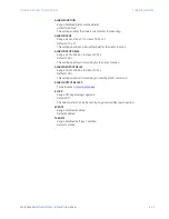
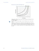
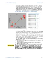
CURVE LIMIT 1(10)
Range: 0.00 to 1.50xVT in steps of 0.01xVT
Default: 0.00xVT
This setting provides the configurable characteristic curve operating limit for the
associated operating time. The curve limit should be equal or in an increasing order for
each consecutive point. For example, if point 4 is at 0.3xVT, point 5 should be greater
than or equal to 0.3xVT.
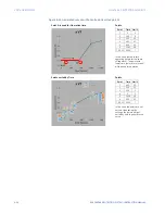
CURVE TIME 1(10)
Range: 0.000 to 600000.000 s in steps of 0.001 s
Default: 2.000 s
This setting provides the configurable characteristic curve operating time for the
associated operating limit. The curve time should be set in an increasing order. For
example, point 1 should start at 0.000s and then point 2 should be at 0.150s.
FASTPATH:
The setting Curve Time 1 should always begin with 0.000 s. All the progressive curve
timings should be in the increasing order. If the curve is not configured properly, the
element may not operate as desired.
BLOCK
Range: Off, Any FlexLogic operand
Default: Off
The Timed UV will be blocked, when the selected operand is asserted.
OUTPUT RELAY X
For details see
EVENTS
Range: Disabled, Enabled
Default: Enabled
The selection of the Enabled setting enables the events of Timed UV function.
TARGETS
Range: Disabled, Self-Reset, Latched
Default: Self-Reset
The selection of the Disabled setting disables the targets of Timed UV function. In self-
reset mode, the targets remain active until function drops out. In latched mode, the
target maintains the set state until deactivated by a reset command.
Summary of Contents for Multilin 850
Page 10: ...VIII 850 FEEDER PROTECTION SYSTEM INSTRUCTION MANUAL ...
Page 135: ...CHAPTER 3 INTERFACES SOFTWARE INTERFACE 850 FEEDER PROTECTION SYSTEM INSTRUCTION MANUAL 3 41 ...
Page 151: ...CHAPTER 3 INTERFACES SOFTWARE INTERFACE 850 FEEDER PROTECTION SYSTEM INSTRUCTION MANUAL 3 57 ...
Page 153: ...CHAPTER 3 INTERFACES SOFTWARE INTERFACE 850 FEEDER PROTECTION SYSTEM INSTRUCTION MANUAL 3 59 ...
Page 439: ...CHAPTER 7 MONITORING FUNCTIONS 850 FEEDER PROTECTION SYSTEM INSTRUCTION MANUAL 7 19 ...
Page 644: ...11 20 850 FEEDER PROTECTION SYSTEM INSTRUCTION MANUAL FLEXELEMENTS CHAPTER 11 METERING ...


