CHAPTER 1: INTRODUCTION
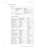
SPECIFICATIONS
850 FEEDER PROTECTION SYSTEM – INSTRUCTION MANUAL
1–27
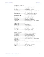
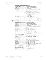
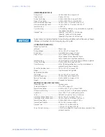
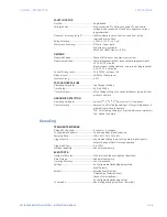
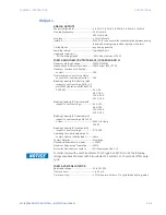
CT SUPERVISION 1 (CTS)
Operating Parameter:.......................................Ia, Ib, Ic and Ig (Fundamental Phasor Magnitude)
Va, Vb, Vc (Fundamental Phasor Magnitude)
3I0 Pickup Level:..................................................0.050 to 30.000 x CT in steps of 0.001 x CT (phase CT)
IG Pickup Level: ....................................................0.050 to 30.000 x CT in steps of 0.001 x CT (ground CT)
3V0 Pickup Level: ................................................0.02 to 3.00 x VT in steps of 0.01 x VT (phase VT)
Dropout Level: ......................................................97% to 98% of Pickup
CTS Diff. Pickup Level: .......................................0.050 to 30.000 x CT in steps of 0.001 x CT
Quotient Pickup Level: ......................................0.00 to 1.00 (lmin/lmax)
Slope Range: .........................................................0 to 100% in steps of 1%
Pickup Delay: ........................................................0.000 to 6000.000 s in steps of 0.001 s
Level Accuracy:....................................................For 0.1 to 2.0 x CT: ±0.5% of reading or ±0.4% of rated
(whichever is greater)
For > 2.0 x CT: ±1.5% of reading
Operate Time:.......................................................< 12 ms typical at 3 x Pickup at 60 Hz
< 15 ms typical at 3 x Pickup at 50 Hz
Timer Accuracy: ..................................................±3% of delay setting or ±¼ cycle (whichever is greater) from
pickup to operate
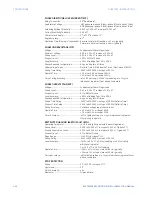
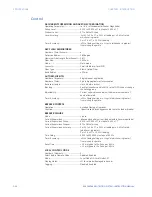
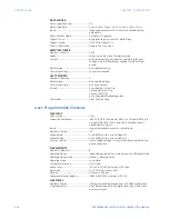
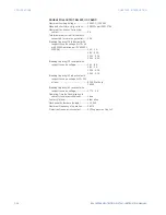
POLE DISCORDANCE PROTECTION (52)
Operating Parameter:.......................................Contact inputs 52a and 52b per phase, Phase currents Ia, Ib,
Ic from breaker CTs
Current Limit: ........................................................0.000 to 1.000 x CT in steps of 0.001 x CT
Dropout Level: ......................................................97 to 98% of Current Limit
Pickup Time Delay:.............................................0.000 to 6000.000 s in steps of 0.001 s
Level Accuracy (Current): ................................0.1 < I < 2.0 x CT: ±0.5% of reading or ±0.4% of rated
(whichever is greater)
I > 2.0 x CT: ±1.5% of reading
Timer Accuracy: ..................................................±3% of operate time or ±1 cycle (whichever is greater)
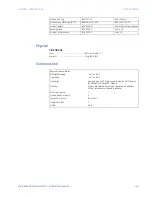
SWITCH CONTROL
Operation:...............................................................Local (PB control and SLD) and Remote (asserted FlexLogic
operands)
Function: .................................................................Opens/Closes the disconnect switch
Timers: .....................................................................0.000 to 6000.000 s in steps of 0.001 s
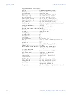
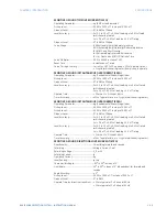
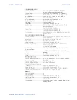
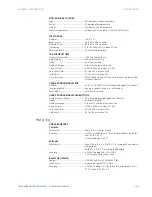
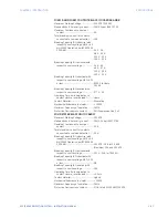
SYNCHROCHECK (25)
Maximum Frequency Difference:................0.01 to 5.00 Hz in steps of 0.01 Hz for frequency window of
f
nom
± 5 Hz
Maximum Angle Difference: ..........................1° to 100° in steps of 1°
Maximum Voltage Difference: ......................10 to 600000 V in steps of 1 V
Hysteresis for Maximum Frequency
Difference:.........................................................0.01 to 0.10 Hz in steps of 0.01 Hz
Breaker Closing Time:.......................................0.000 to 6000.000 s in steps of 0.001 s
Dead Source Function:.....................................None, LB & DL, DB & LL, DB & DL, DB OR DL, DB XOR DL
Dead/Live Levels for Bus and Line:.............0.00 to 1.50 x VT in steps of 0.01 x VT
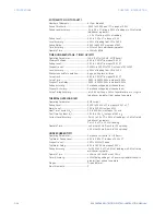
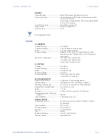
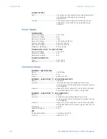
TRIP BUS
Number of Elements: ........................................6
Number of Inputs:...............................................16
Pickup Time Delay:.............................................0.000 to 6000.000 s in steps of 0.001 s
Dropout Time Delay: .........................................0.000 to 6000.000 s in steps of 0.001 s
Operate Time:.......................................................< 2 ms at 60 Hz
Timer Accuracy: ..................................................± 3% of delay time or ± ¼ cycle (whichever is greater) from
pickup to operate
Summary of Contents for Multilin 850
Page 10: ...VIII 850 FEEDER PROTECTION SYSTEM INSTRUCTION MANUAL ...
Page 135: ...CHAPTER 3 INTERFACES SOFTWARE INTERFACE 850 FEEDER PROTECTION SYSTEM INSTRUCTION MANUAL 3 41 ...
Page 151: ...CHAPTER 3 INTERFACES SOFTWARE INTERFACE 850 FEEDER PROTECTION SYSTEM INSTRUCTION MANUAL 3 57 ...
Page 153: ...CHAPTER 3 INTERFACES SOFTWARE INTERFACE 850 FEEDER PROTECTION SYSTEM INSTRUCTION MANUAL 3 59 ...
Page 439: ...CHAPTER 7 MONITORING FUNCTIONS 850 FEEDER PROTECTION SYSTEM INSTRUCTION MANUAL 7 19 ...
Page 644: ...11 20 850 FEEDER PROTECTION SYSTEM INSTRUCTION MANUAL FLEXELEMENTS CHAPTER 11 METERING ...

