8–34
850 FEEDER PROTECTION SYSTEM – INSTRUCTION MANUAL
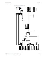
ARC FLASH PROTECTION
CHAPTER 8: CONTROL
Arc Flash Protection
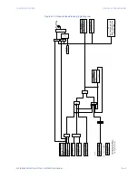
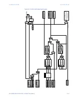
The Arc Flash Protection module supports fast and secure protection against an arc flash
event for a safe working environment.
Arc Flash protection utilizes a total of four light detection fiber sensors and dedicated high-
speed instantaneous overcurrent element with secure Finite Response Filtering. Light from
the light sensor AND logic with high-speed overcurrent ensures fast and secure operation.
Further enhancement includes continuous monitoring of individual light sensors with self-
test trouble indication. Four Arc Flash elements with self-test from the individual light
sensors can be used to design flexible Arc Flash protection schemes for different
configurations depending upon the physical locations of the sensors. Each individual
element can also provide a higher level of redundancy/reliability of the system.
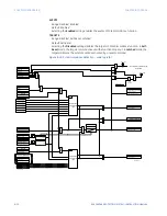
In case any issues with the sensors are detected (i.e. failure of a self-test), the
corresponding light sensor trouble operands (i.e. “Light Sensor # Trouble” and “Light Sensor
Trouble”) are asserted. Very fast detection of the Arc flash light event is also possible using
Light as the only detection parameter for alarm purposes. In addition, customized logic
can be designed using individual “AF1 Light # PKP” and “Arc Flash 1 S# OP” operands from
different light sensors in the FlexLogic engine.
Path
:
Setpoints > Control > Arc Flash > Arc Flash 1
FUNCTION
Range: Disabled, Trip, Alarm, Latched Alarm, Configurable
Default: Disabled
The selection of Trip, Alarm, Latched Alarm or Configurable setting enables the HS
Phase/Ground IOC function.
SIGNAL INPUT
Range: dependant upon the order code
Default: CT Bank 1 - J1
This setting provides the selections for the current input bank. The default bank names
can be changed in: Setpoints > System > Current Sensing > [Name] > CT Bank Name.
HS PHASE PKP
Range: 0.050 to 30.000 x CT in steps of 0.001 x CT
Default: 2.000 x CT
HS GROUND PKP
Range: 0.050 to 30.000 x CT in steps of 0.001 x CT
Default: 1.000 x CT
NOTE
NOTE:
The value of HS Gnd PICKUP can be set to a very high value, when only the HS Phs element
needs to be applied for Arc Flash detection.
NOTE
NOTE:
The HS Ground PKP setting is not available if the order code is selected to have just one
sensitive ground current input on the J1-Bank (4-0B in the order code).
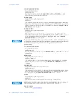
LIGHT SENSOR 1(4)
Range: Disabled, Enabled
Default: Disabled
BLOCK
Range: Off, Any FlexLogic operand
Default: Off
OUTPUT RELAY X
For details see
Summary of Contents for Multilin 850
Page 10: ...VIII 850 FEEDER PROTECTION SYSTEM INSTRUCTION MANUAL ...
Page 135: ...CHAPTER 3 INTERFACES SOFTWARE INTERFACE 850 FEEDER PROTECTION SYSTEM INSTRUCTION MANUAL 3 41 ...
Page 151: ...CHAPTER 3 INTERFACES SOFTWARE INTERFACE 850 FEEDER PROTECTION SYSTEM INSTRUCTION MANUAL 3 57 ...
Page 153: ...CHAPTER 3 INTERFACES SOFTWARE INTERFACE 850 FEEDER PROTECTION SYSTEM INSTRUCTION MANUAL 3 59 ...
Page 439: ...CHAPTER 7 MONITORING FUNCTIONS 850 FEEDER PROTECTION SYSTEM INSTRUCTION MANUAL 7 19 ...
Page 644: ...11 20 850 FEEDER PROTECTION SYSTEM INSTRUCTION MANUAL FLEXELEMENTS CHAPTER 11 METERING ...


