CHAPTER 8: CONTROL
AUTORECLOSE
850 FEEDER PROTECTION SYSTEM – INSTRUCTION MANUAL
8–79
Autoreclose
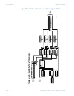
The 850 relay provides up to two Autoreclose (AR1) elements. The Autoreclose scheme
provides flexibility that allows the application of many typical distribution and
subtransmission control strategies.
Up to four reclosing ‘shots’ with separately programmable ‘dead times’ can be set for each
shot. Reclosing can be initiated from any 850 Overcurrent element, or from external
sources. Overcurrent protection setpoints can be adjusted between reclosing shots in
order to co-ordinate with downstream devices. To prevent breaker wear, a ‘current
supervision’ feature can reduce the number of shots when the fault current is high. A ‘zone
co-ordination’ feature is provided for protection coordination with downstream reclosers.
Inputs for blocking and disabling the scheme are available.
Front panel LEDs indicate the present state of the Autoreclose scheme:
1.
Reclosure Enabled: The scheme is enabled and may reclose if a Trip occurs.
2.
Reclosure in Progress: An Autoreclosure has been initiated but the breaker has not yet
been closed.
3.
Reclosure Lockout: The scheme has generated the maximum number of breaker
closures allowed and, as the fault persists, will not close the breaker again. The
scheme has gone to ‘Lockout’ and must be reset before further reclosures are
permitted. The scheme may also be sent into ‘Lockout’ when the incomplete
sequence timer times out or when a block/cancel or breaker failure signal occurs
while in ‘Reclose in Progress’. If enabled, the Lockout from the Rate Supervision
function or the Lockout from the Zone Coordination function may also send the
scheme to Lockout. The scheme must be reset from Lockout in order to perform a
Reclose for further faults.
FASTPATH:
STATUS / AUTORECLOSE 1 can also be accessed to determine the present state of the
Autoreclose scheme.
The scheme is considered enabled when all of the following four conditions are true:
1.
The AR1 FUNCTION setpoint is set to “Enabled”.
2.
AR1 BLOCK/CANCEL input function is not asserted.
3.
The scheme is not in the Lockout state.
4.
The ‘AR1 Block Time Upon Manual Close’ timer is not active.
The Autoreclose scheme is initiated by a Trip signal from any selected protection feature
operand or by external initiation. The scheme is initiated provided the circuit breaker is in
the CLOSED state before protection operation.
The Reclose-In-Progress (RIP) is set when a reclosing cycle begins following a Reclose
Initiate signal. Once the cycle is successfully initiated, the RIP signal will seal-in and the
scheme will continue through its sequence until one of the following conditions is satisfied:
1.
The Close signal is issued when the dead timer times out
Summary of Contents for Multilin 850
Page 10: ...VIII 850 FEEDER PROTECTION SYSTEM INSTRUCTION MANUAL ...
Page 135: ...CHAPTER 3 INTERFACES SOFTWARE INTERFACE 850 FEEDER PROTECTION SYSTEM INSTRUCTION MANUAL 3 41 ...
Page 151: ...CHAPTER 3 INTERFACES SOFTWARE INTERFACE 850 FEEDER PROTECTION SYSTEM INSTRUCTION MANUAL 3 57 ...
Page 153: ...CHAPTER 3 INTERFACES SOFTWARE INTERFACE 850 FEEDER PROTECTION SYSTEM INSTRUCTION MANUAL 3 59 ...
Page 439: ...CHAPTER 7 MONITORING FUNCTIONS 850 FEEDER PROTECTION SYSTEM INSTRUCTION MANUAL 7 19 ...
Page 644: ...11 20 850 FEEDER PROTECTION SYSTEM INSTRUCTION MANUAL FLEXELEMENTS CHAPTER 11 METERING ...


