2–34
850 FEEDER PROTECTION SYSTEM – INSTRUCTION MANUAL
ELECTRICAL INSTALLATION
CHAPTER 2: INSTALLATION
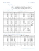
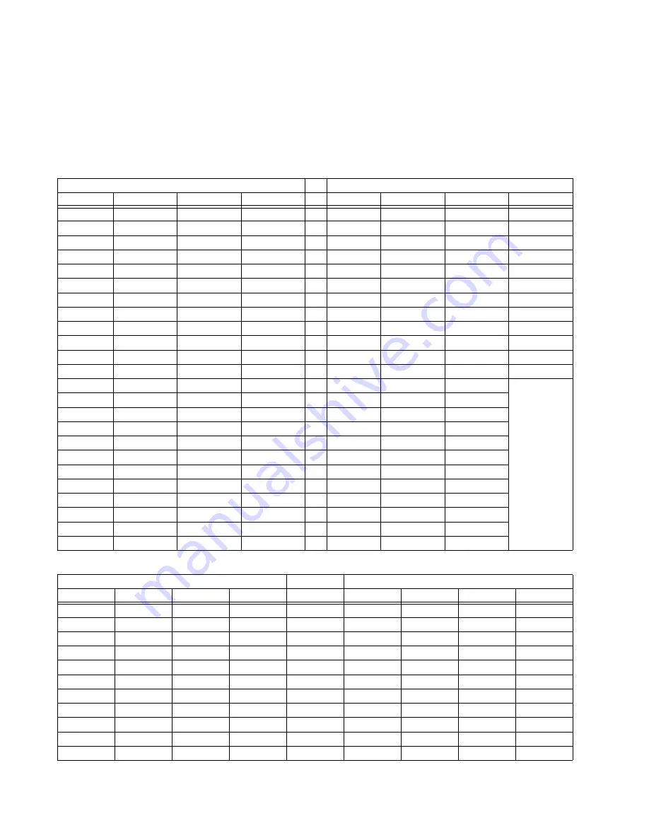
Output Relays
The locations of the output relays have a fixed assignment for the platform called the
master identifier. I/O options that include inputs occupy the fixed assigned output
locations so in these cases the relay assignment maps to the master identifier.
The critical failure output relay is reserved as Relay_8 and it is omitted and is not
programmable.
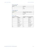
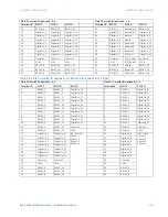
Table 2-6: Slots F,G,H Terminal Master Identifier (left) and I/O options A,A,N (right)
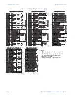
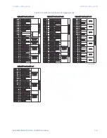
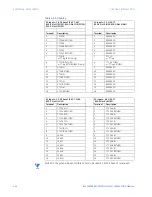
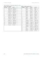
Table 2-7: Slots F, G, H with I/O options A, A, A (left) and I/O options A, L, A (right)
Slots F, G, H Terminal Master Identifier
Slots F, G, H with I/O options M, L, F
Terminal #
SLOT F
SLOT G
SLOT H
Terminal #
SLOT F
SLOT G
SLOT H
1
RELAY_1
RELAY_9
RELAY_17
1
RELAY_1
Analog Out_1
Digital In_8
2
RELAY_1
RELAY_9
RELAY_17
2
RELAY_1
Analog Out_2
Digital In_9
3
RELAY_1
RELAY_9
RELAY_17
3
RELAY_1
Analog Out_3
Digital In_10
4
RELAY_2
RELAY_10
RELAY_18
4
RELAY_2
Analog Out_4
Digital In_11
5
RELAY_2
RELAY_10
RELAY_18
5
RELAY_2
Analog Out_5
Digital In_12
6
RELAY_2
RELAY_10
RELAY_18
6
RELAY_2
Analog Out_6
Digital In_13
7
RELAY_3
RELAY_11
RELAY_19
7
RELAY_3
Analog Out_7
Digital In_14
8
RELAY_3
RELAY_11
RELAY_19
8
RELAY_3
Return
Digital In_15
9
RELAY_3
RELAY_11
RELAY_19
9
RELAY_3
Shield
Digital In_16
10
RELAY_4
RELAY_12
RELAY_20
10
RELAY_4
Analog In_1
Digital In_17
11
RELAY_4
RELAY_12
RELAY_20
11
RELAY_4
Analog In_2
Common
12
RELAY_4
RELAY_12
RELAY_20
12
RELAY_4
Analog In_3
+24V
13
RELAY_5
RELAY_13
RELAY_21
13
Digital In_1
Analog In_4
ARC FLASH
Sensor 1
Sensor 2
Sensor 3
Sensor 4
14
RELAY_5
RELAY_13
RELAY_21
14
Digital In_2
Return
15
RELAY_5
RELAY_13
RELAY_21
15
Digital In_3
Shield
16
RELAY_6
RELAY_14
RELAY_22
16
Digital In_4
Reserved
17
RELAY_6
RELAY_14
RELAY_22
17
Digital In_5
Reserved
18
RELAY_6
RELAY_14
RELAY_22
18
Digital In_6
Reserved
19
RELAY_7
RELAY_15
RELAY_23
19
Digital In_7
RTD_Hot
20
RELAY_7
RELAY_15
RELAY_23
20
Common
RTD_Comp
21
RELAY_7
RELAY_15
RELAY_23
21
+24V
RTD_Return
22
RELAY_8
RELAY_16
RELAY_24
22
RELAY_8
Shield
23
RELAY_8
RELAY_16
RELAY_24
23
RELAY_8
Reserved
24
RELAY_8
RELAY_16
RELAY_24
24
RELAY_8
Reserved
Slots F,G,H with I/O options A, A, A
Slots F,G,H with I/O options A, L, A
Terminal #
SLOT F
SLOT G
SLOT H
Terminal #
SLOT F
SLOT G
SLOT H
1
RELAY_1
RELAY_9
RELAY_17
1
RELAY_1
Analog Out_1 RELAY_9
2
RELAY_1
RELAY_9
RELAY_17
2
RELAY_1
Analog Out_2 RELAY_9
3
RELAY_1
RELAY_9
RELAY_17
3
RELAY_1
Analog Out_3 RELAY_9
4
RELAY_2
RELAY_10
RELAY_18
4
RELAY_2
Analog Out_4 RELAY_10
5
RELAY_2
RELAY_10
RELAY_18
5
RELAY_2
Analog Out_5 RELAY_10
6
RELAY_2
RELAY_10
RELAY_18
6
RELAY_2
Analog Out_6 RELAY_10
7
RELAY_3
RELAY_11
RELAY_19
7
RELAY_3
Analog Out_7 RELAY_11
8
RELAY_3
RELAY_11
RELAY_19
8
RELAY_3
Return
RELAY_11
9
RELAY_3
RELAY_11
RELAY_19
9
RELAY_3
Shield
RELAY_11
10
RELAY_4
RELAY_12
RELAY_20
10
RELAY_4
Analog In_1
RELAY_12
11
RELAY_4
RELAY_12
RELAY_20
11
RELAY_4
Analog In_2
RELAY_12
Summary of Contents for Multilin 850
Page 10: ...VIII 850 FEEDER PROTECTION SYSTEM INSTRUCTION MANUAL ...
Page 135: ...CHAPTER 3 INTERFACES SOFTWARE INTERFACE 850 FEEDER PROTECTION SYSTEM INSTRUCTION MANUAL 3 41 ...
Page 151: ...CHAPTER 3 INTERFACES SOFTWARE INTERFACE 850 FEEDER PROTECTION SYSTEM INSTRUCTION MANUAL 3 57 ...
Page 153: ...CHAPTER 3 INTERFACES SOFTWARE INTERFACE 850 FEEDER PROTECTION SYSTEM INSTRUCTION MANUAL 3 59 ...
Page 439: ...CHAPTER 7 MONITORING FUNCTIONS 850 FEEDER PROTECTION SYSTEM INSTRUCTION MANUAL 7 19 ...
Page 644: ...11 20 850 FEEDER PROTECTION SYSTEM INSTRUCTION MANUAL FLEXELEMENTS CHAPTER 11 METERING ...


