102
GE INFORMATION
D400 SUBSTATION GATEWAY INSTRUCTION MANUAL
CHAPTER 7: SETTING UP THE D400 FOR REDUNDANCY
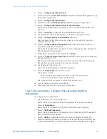
22. Enter
6. Configure Time Sync with Standby
. (Optional)
Skip this option if both D400s are already in time-sync through other means (for
example, IRIG-B or NTP).
23. Enter
7. Configure Enable/Disable DTAs in Standby
.
Result: The D400 Redundancy Configuration Menu - Enable/Disable DTAs on Standby
menu appears.
If the “Enable/Disable DTAs in Standby” parameter is set to Enabled, the LogicLinx,
Calculator and Enhanced Automation DTAs run normally on the standby D400. If this
parameter is set to Disabled, these applications suspend processing on the standby
D400 and resume normal operations when the D400 state becomes active.
Skip this option if DTA applications (that is, automation applications such as LogicLinx,
Calculator, Enhanced Automation) on the Standby D400 are to run (default option).
24. Enter
8. Configure D400 A/B Designation
.
Result: The D400 Redundancy Configuration Menu - Redundancy D400 Designation
(A/B) Configuration menu appears.
25. Follow the provided instructions and enter
1. D400_A
.
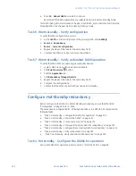
26. Enter
9. Setup Public Key Authentication with Peer D400
.
26.1. Enter
Y
to copy the public key of this D400 to peer the D400.
26.2. Enter the password of the user defined in the peer D400. This option exchanges
the public and private keys.
27. Enter
10. Configure Switch Panel Type
.
Skip this step if the Switch Panel serial connection is not configured. Otherwise, go
through the instructions provided and make your selection.
28. Enter
11. Enable/Disable Non-Sync mode
.
29. Default option: The D400 in Hot-Standby mode runs with Non-Sync Mode Enabled.
You can disable this mode.
30. Enter either:
–
Y
to disable Non-Sync Mode.
–
N
to continue operation with the default option (Non-Sync mode enabled).
31. Navigate back to the main menu.
32. Enter
19. Reboot D400
and wait for a minute.
33. Result: This:
–
Restarts all of the applications and runs them in Hot-Standby mode.
–
Starts the ACTIVE D400 in Hot Standby Mode.
Result: After the first D400 is configured, it enters into the Active mode.
34. Login to the peer D400 and execute d400cfg.
35. Repeat the steps of Task 4 to configure the peer D400.
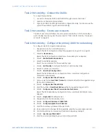
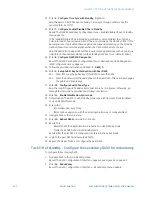
Task 5: Hot standby - Configure the secondary D400 for redundancy
To configure the secondary D400:
1.
Navigate back to the main d400cfg menu.
Result: The D400 Configuration Utility Menu appears. See Figure 52 on page 92.
2.
Enter
14. Redundancy
.
Result: The D400 Configuration Utility Menu - Redundancy menu appears.
Summary of Contents for Multilin D400
Page 12: ...12 GE INFORMATION D400 SUBSTATION GATEWAY INSTRUCTION MANUAL PRODUCT SUPPORT ...
Page 28: ...28 GE INFORMATION D400 SUBSTATION GATEWAY INSTRUCTION MANUAL CHAPTER 1 BEFORE YOU START ...
Page 34: ...34 GE INFORMATION D400 SUBSTATION GATEWAY INSTRUCTION MANUAL CHAPTER 2 INSTALLING THE D400 ...
Page 88: ...88 GE INFORMATION D400 SUBSTATION GATEWAY INSTRUCTION MANUAL CHAPTER 5 POWERING UP THE D400 ...
Page 174: ...174 GE INFORMATION D400 SUBSTATION GATEWAY INSTRUCTION MANUAL APPENDIX A STANDARDS PROTECTION ...
Page 184: ...184 GE INFORMATION D400 SUBSTATION GATEWAY INSTRUCTION MANUAL APPENDIX C LIST OF ACRONYMS ...
Page 192: ...192 GE INFORMATION D400 SUBSTATION GATEWAY INSTRUCTION MANUAL INDEX ...


