42
GE INFORMATION
D400 SUBSTATION GATEWAY INSTRUCTION MANUAL
CHAPTER 3: SETTING UP COMMUNICATION CARDS
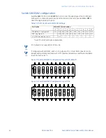
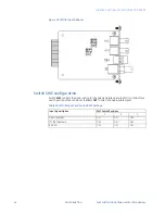
Switch SW3/SW4 configuration
Switches
SW3
(for Channel 2 on TB1-6 through TB1-10) and
SW4
(for Channel 1 on TB1-1
through TB1-5) contain ten DIP-switches that control RS-422 pull-up and pull-down
resistors for the differential data lines and provide line termination between the differential
data pairs. Each DIP-switch can be set to
ON
or
OFF
to select the appropriate function for
the switch. That is, if all pins are set to
ON
, switch is ON. If all pins are set to
OFF
, switch is
OFF.
If RS-422 termination/pull-up is selected, the TX+ and RX+ signals have a 680 ohm pull-up
resistor, the TX- and RX- signals have a 680 ohm pull-down resistor, and the RX and TX
signals have a 120 ohm termination.
Figure 17: RS-485 Mode - 12 KOhm (Single Unit Load))
Figure 18: RS-422 120 Ohm Line Termination on TX and RX
Figure 19: RS-422 120 Ohm Line Termination with 680 Ohm Pull-Up and Pull-Down
Resistors
1
2
3
ON
4
5
6
7
8
9
0
1
2
3
ON
4
5
6
7
8
9
0
1
2
3
ON
4
5
6
7
8
9
0
Summary of Contents for Multilin D400
Page 12: ...12 GE INFORMATION D400 SUBSTATION GATEWAY INSTRUCTION MANUAL PRODUCT SUPPORT ...
Page 28: ...28 GE INFORMATION D400 SUBSTATION GATEWAY INSTRUCTION MANUAL CHAPTER 1 BEFORE YOU START ...
Page 34: ...34 GE INFORMATION D400 SUBSTATION GATEWAY INSTRUCTION MANUAL CHAPTER 2 INSTALLING THE D400 ...
Page 88: ...88 GE INFORMATION D400 SUBSTATION GATEWAY INSTRUCTION MANUAL CHAPTER 5 POWERING UP THE D400 ...
Page 174: ...174 GE INFORMATION D400 SUBSTATION GATEWAY INSTRUCTION MANUAL APPENDIX A STANDARDS PROTECTION ...
Page 184: ...184 GE INFORMATION D400 SUBSTATION GATEWAY INSTRUCTION MANUAL APPENDIX C LIST OF ACRONYMS ...
Page 192: ...192 GE INFORMATION D400 SUBSTATION GATEWAY INSTRUCTION MANUAL INDEX ...


