104
GENERAL
D400 SUBSTATION GATEWAY USER’S MANUAL
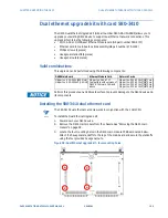
DUAL ETHERNET UPGRADE KIT WITH CARD 580-2717
CHAPTER 8: SERVICING THE D400
5.
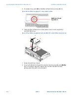
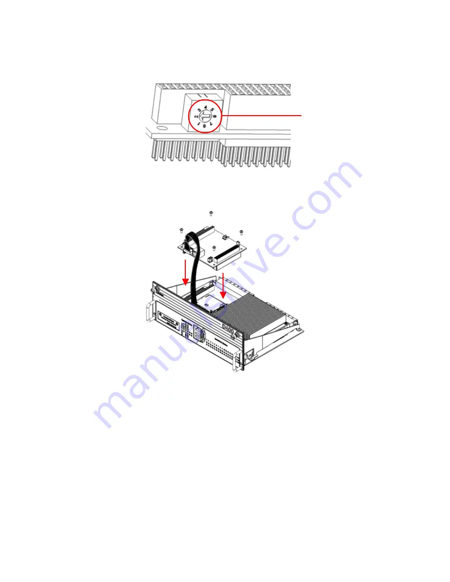
Ensure that rotary switch
U11
on the Ethernet Module card is set to position
2
.
Figure 56: Dual Ethernet upgrade kit - rotary switch position
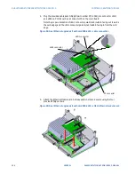
6.
Attach the Ethernet Module card to the expansion slot and secure using the four
provided Philips screws.
Figure 57: Dual Ethernet upgrade kit with card 580-2717 - attach Ethernet module card
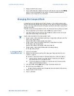
7.
Replace the D400 main module.
8.
Power up the D400 and configure the network connections as required using
d400cfg
.
Refer to the
D400 Configuration Utility
section in the D400 Substation Gateway
Software User’s Manual for more information.
Switch must be set
to position 2


