CHAPTER 3: SETTING UP COMMUNICATION CARDS
IRIG-B INPUT ADAPTER
D400 SUBSTATION GATEWAY USER’S MANUAL
GENERAL
43
NOTE
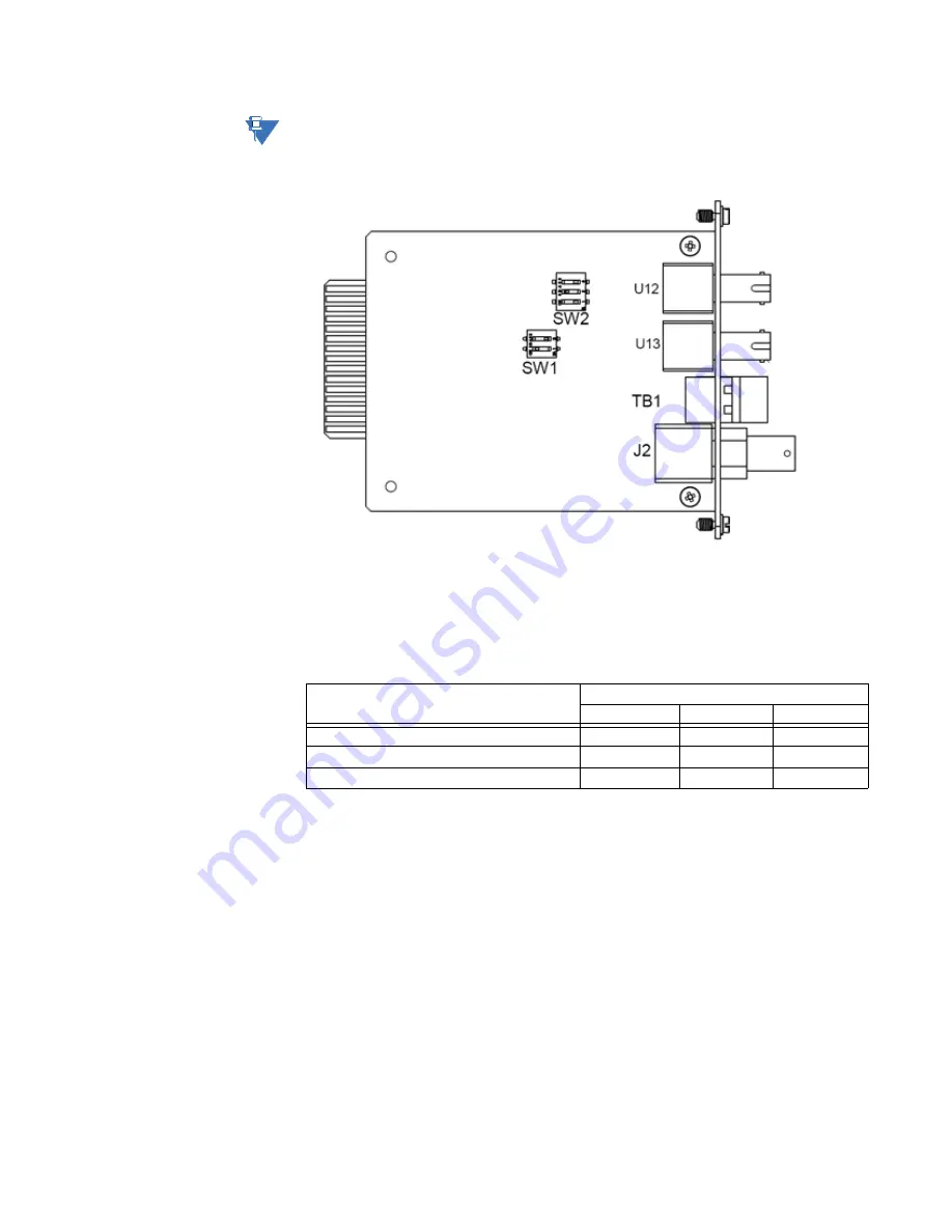
Leave switch
SW1
in the Standard position as it is required for the D400 to properly decode
and set the system time.
Figure 21: IRIG-B Input Adapter
Switch SW2 configuration
Switch
SW2
controls the signal option for the selected state option (SW1). It contains three
switch positions that can be set to
ON
or
OFF
to select the appropriate signal.
Table 9: IRIG-B Input Card Switch SW2 Settings
Input Signal Option
SW2 Switch Positions
1
2
3
Fiber Optic (RX)
ON
OFF
OFF
TTL (TB1) (default)
OFF
ON
OFF
BNC (J2)
OFF
OFF
ON


