GEK-106426B
MIB High Impedance Bus Differntial Relay
6-5
6 I/0 CONFIGURATION
6.2 OUTPUTS AND LEDS CONFIGURATION
6
6.2OUTPUTS AND LEDS CONFIGURATION
6.2.1 DESCRIPTION OF OUTPUTS AND LEDS
MIB incorporates 6 outputs and 6 LED indicators. 4 of the outputs and LED indicators are user configurable, and can only
be programmed using ENERVISTA MII SETUP software (SETPOINT – RELAY CONFIGURATION). The first two LEDs
are fixed for READY (System ready) and TRIP. The fixed outputs are programmed for ALARM (System alarm) and TRIP.
The TRIP LED activates when the TRIP contact closes.
The READY LED turns on when all the following conditions are fulfilled:
•
The relay status is READY
•
At least one of the protection functions of the active table is enabled
•
The trip of at least one of the enabled functions is also enabled.
The default configuration for outputs is as follows:
The default LED configuration is as follows:
Outputs/LEDs can be configured to be activated by a single element or by a sum of several of them. These elements are
divided into eight groups, besides the
No definition
element. Elements belonging to the same group can be assigned to
the same output/LED. Elements of different groups need to be assigned to different outputs/LEDs.
In order to assign several elements to activate an output/LED, we first activate the
OR
button, next, click on the
I/O
CONFIGURATION
frame and select the desired element group, then choose the desired elements. In order to invert an
element, select the
NOT
button. Finally, click on the
OK
button.
The Output/LED logic can inverted selecting the general
NOT
button. Outputs can be latched, and LEDs can be set to be
fixed or blinking.
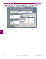
Example:If we want to assign a phase A (High or low level) differential trip to an output or LED, the output or LED must
be programmed with 87 1 function trip and 87 2 function trip.To do this, check the OR box in the corresponding Output or
LED line (for this case, Output1 and LED1). Then click on the OR button that appears in the I/O configuration column,
select the desired group (
TRIP 1
and click the I/O configuration box for every element that will be blocked by the input.
OUTPUT
CONFIGURATION
MEMORY
1
87 1 Trip
No
2
87 2 Trip
No
3
Reset 86
No
4
Trip
No
LED
CONFIGURATION
MEMORY
3000
1000 & 2000
1
Phase A Trip
87 1 Trip
Yes
2
Phase B Trip
87 2 Trip
Yes
3
Phase C Trip
87 1 Pickup
Yes
4
General Pickup
87 2 Pickup
No


