GEK-106426B
MIB High Impedance Bus Differntial Relay
3-11
3 HARDWARE
3.4 HIGH-SPEED OVERCURRENT PROTECTION MODULE
3
3.4.5 OUTPUT CONTACTS CONFIGURATION
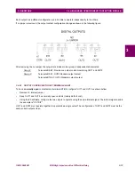
MIB relays provide one trip contact, one alarm (system ready) contact and four auxiliary contacts sharing one common
located in the high-speed overcurrent module. All output relays are form C relays.All output relays are form C relays. Only
one of the two states of the form C relay is connected to the output terminal. For each output relay it is possible to select
which state is preferred to have at the
terminals, NC (normally closed) or NO (normally open).
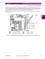
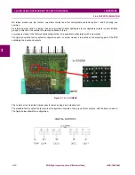
Next figure shows the PCB of a MIB
relay, and the location of the jumpers used to select the configuration of each output
contact (NO or NC).
Figure 3–11: PCB SCHEME SHOWING THE JUMPERS TO CONFIGURE THE OUTPUT CONTACTS (NC / NO)


