GEK-113188A
MIGII Digital Protection for Electrical Machines
2-19
2 PRODUCT DESCRIPTION
2.14 USER INTERFACE
2
2.14USER INTERFACE
2.14.1 LED TARGETS
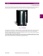
There are 6 LED Targets in the front of the relay. The first one is green (‘READY’ -relay in service-) and cannot be
configured; the second one is red and fixed for trip, while the other 4 can be configured by the user in OPTION1 and
OPTION2 models. The default configuration of the LEDs is shown in the following figure.
Figure 2–5: LEDS DEFAULT CONFIGURATION
It is possible to configure the color of the 4 configurable LEDs between red and green using the keypad of the front panel of
the relay (for details, refer to Chapter
The indication of each LED inis as follows:
READY:
The relay is powered up, its power supply is receiving Vdc or Vac, and all the internal circuits are
working properly. The relay status setting is set as “RDY” (ready) and at least one of the protection
functions is enabled. If the LED is off with the above-mentioned conditions, this indicates a loss of
auxiliary supply voltage or an internal HW/SW critical failure condition.
TRIP:
The relay has issued a trip, activating the corresponding tripping output contact.
THERMAL:
The trip has been issued by the Thermal Image element (49)
OVERCURRENT:
The trip has been issued by one of the overcurrent elements (50P, 50G, 51P, 51G)
UNBALANCE:
the trip has been issued by the current unbalance element (46)
PICKUP:
Indicates that at least one of the protective elements has picked up.
LEDs associated to tripping functions are latched and once they have been turned on, they remain on until the ESC/RESET
button is pressed for more than 3 seconds (RESET) providing that the trip condition has disappeared. The LED associated
to
function pickup
is self-reset type, and stays on while the pickup condition (current above setting) exists.
2.14.2 KEYPAD AND DISPLAY
A five-button keypad allows access to MIGII relay information and settings changes. Measurement data (actual values),
five last trip information (fault reports) and settings are shown on the 16x2 character LCD display.
The keypad includes the functionality to modify the contrast of the display (refer to Chapter 8 for details).
The event list, oscillography, I/O and logic configuration can be accessed only from the ENERVISTA MII SETUP program.
2.14.3 COMMUNICATION PORTS
The front RS232 and the rear RS485 port provide interface with the relay. All serial ports use the Modbus® RTU protocol
and may be connected to system computers with baud rates from 300 to 19200 bps. Up to 32 MIGII relays can be
connected (daisy-chained) on the same communication circuit. Each relay must be assigned a different Modbus Address
(using a setting) if multiple relays are connected on the same circuit.
Summary of Contents for Multilin MIGII
Page 2: ......

