background image


NX-8E CONTROL 

9

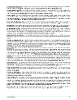
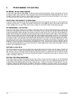
CHANGING USER CODES: 

1)  Enter [

r

]-[5]-[master code] - The "Ready" LED will flash.  

2)  Enter the 3 digit user number (i.e. “003 for user 3). Maximum number of users is 240. 
3)  Enter the new user code designated for that individual - The "Ready" LED will flash indicating that the code 

was accepted.  If it rejects the code, the sounder will beep 3 times, 


4)  If another user code needs to be programmed, return to step 2. 
5)  Press [#] while the "Ready" LED is flashing to exit the User Code Programming Mode. 

 
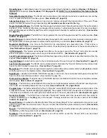
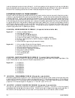
ASSIGNING AUTHORITY LEVEL:
 

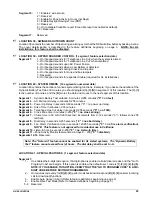
1) Enter [

r

]-[6]-[master code] - The "Ready" LED will flash.  


2) Enter [3 digit user number] (always 3 digits such as “003” for user 3) - The "Ready" LED will illuminate 

steady and the "Instant" LED will flash.  Refer to the chart below for the description of each LED. Turn the 
LED on for the features that you desire


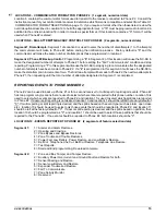
LED 


ATTRIBUTES IF LED 8 IS OFF 


LED 


ATTRIBUTES IF LED 8 IS ON 


Reserved 


Activate output #1 


Arm Only 


Activate output # 2 


Arm Only After Close Window 


Activate output # 3 


Master arm/disarm (can program other codes) 


Activate output # 4 


Arm/disarm code 


Arm/disarm 


Allowed to bypass zones (see location 23) 


Bypass Zones 


Code will send open / close reports 


Open / Close Reporting 


If this LED is on, LEDs 1-7 will use the chart to the right 


If this LED is off, LEDs 1-7 use the chart to the left


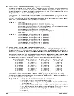
3) Enter [

r

] - The "Instant" LED will illuminate steady. 

This moves you to the partition enable.  (This tells the system what partition this user can arm/disarm.  
LEDs 1-8 illuminate for each partition that the user has authorization for.  To change any of these 
numbers, press 1-8 to permit or deny access to the user.   (Example: If LED #2 is lit, then user has 
assigned access to that partition.  By pressing the [2] key, the LED will go off indicating the user has 
been denied access to that partition.)   

4) Enter [

r

This returns you back to step 2 above.  At this point you may enter another user number to assign 
attributes for.  You may continue this procedure until you have assigned authority levels to all user 
numbers  - or - you may press [#] key to exit the Assigning Authority Level Program. 

 
NOTE: Any master arm/disarm code can add or change a user code if the master code has access to the 

same partitions as the code being added/changed.  Consequently, when programming the user codes 
for a partitioned system
leave at least one code (can be "go to program code" if enabled in location 
43) access to all partitions or you will not be able to add new users.  If you desire the end user to be 
able to add new codes, you must remove the partition authority from all blank codes.


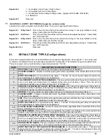
[

r

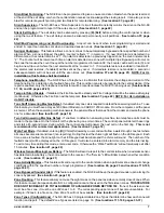
]-[9]-[8]  

Pressing [

r

]-[9]-[8] while the system is disarmed will cause the control to do a callback for a download. 

NOTE: A valid user code may be required after [

r

]-[9]-[8] if enabled in location 41, page 23. 

 
[

r

]-[9]-[9]  

Pressing [

r

]-[9]-[9] while the system is disarmed will cause the control panel to seize the phone line for a 

download. NOTE: A valid user code may be required after [

r

]-[9]-[9] if enabled in location 41. 

Summary of Contents for NetworX NX-8E

Page 1: ...NetworX Series NX 8E Control Panel Installation and Startup ...

Page 2: ...ary information of GE Interlogix USA and is furnished to its customer solely to assist that customer in the installation testing operations and or maintenance of the equipment described This document shall not be reproduced in whole or in part nor shall its contents be disclosed to any third party without the written approval of GE Interlogix Please refer to the current GE Interlogix product catal...

Page 3: ...QUICK START INSTALLATION 12 X PROGRAMMING LOCATIONS 13 Table X 1 COMMUNICATOR FORMAT SELECTIONS 13 REPORTING EVENTS TO PHONE NUMBER 1 14 REPORTING EVENTS TO PHONE NUMBER 2 15 REPORTING EVENTS TO PHONE NUMBER 3 16 XI DEFAULT ZONE TYPES Configurations 19 Table XI 1 AUXILIARY OUTPUT EVENT SELECTION 25 XII PROGRAMMING WORKSHEETS 45 XIII NX 8E WIRING DIAGRAM 66 XIV TERMINAL DESCRIPTIONS 67 KEYPAD MAXIM...

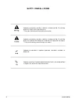
Page 4: ...ution Indicates a procedure practice condition or statement that if not strictly observed could result in damage to or destruction of equipment or property This symbol indicates general warnings and cautions Note Indicates an essential or important procedure instruction condition or statement Tip Indicates a user tip Provides helpful information that is not normally defined in regular use but from...

Page 5: ... KIT NX 8E Control NX 148E LCD Keypad 16 5V 40VA Transformer NX 108E 8 Zone LED Keypad NX 116E 16 Zone LED Keypad NX 124E 24 Zone LED Keypad NX 148E Alphanumeric LCD Keypad NX 200 Zone Doubling Kit Includes 100 3 74k and 100 6 98k resistors NX 216E 16 Zone Expander Module NX 320E Smart Power Supply and Buss Extender NX 408E 8 Zone Wireless Expansion Module UL LISTED PART 60 904 NX 416E 16 Zone Wir...

Page 6: ...on is not required The Cancel and Abort features in locations 23 and 40 respectively must be enabled to permit this Auto feature to work For proper operation of these features ADialer Delay must be enabled in the ACharacteristic Select of locations 110 169 Zone Types See location 41 page 23 Automatic Bypass Instant Arming When enabled the control panel can automatically bypass interior follower zo...

Page 7: ... be programmed as supervised Entry Guard This unique low level arming mode has been developed to reduce the most common source of false alarms When armed with the AInstant LED on the opening of any zones designated as Entry Guard zone will initiate the keypad sounder and start the entry delay before creating an alarm All other zones will function as normal This arming mode will encourage system ow...

Page 8: ...ge 18 Log Full Report A report can be sent to the central station when the event log is full See location 37 page 21 Lost Clock Service Light The NX 8E can be programmed to illuminate the Service LED when the internal clock has an invalid time due to power loss See location 37 page 22 Manual Test The NX 8E can be programmed to perform a bell and or communicator test when r 4 4 is entered while the...

Page 9: ...efeat If enabled only one call is required to defeat the answering machine To use this feature you must have a Hayes 1200 Smart Modem or a CADDX 1200 module From the computer call the panel as normal When the answering machine answers the panel will hear the tones from the modem and seize the phone line for a download See location 21 page 18 Two Call Answering Machine Defeat If enabled to defeat a...

Page 10: ... Enable Armed Status Suppression will not allow the keypad to display faulted or bypassed zones when the system is armed 6 Enable Panic Fire Medical Beeptone will sound a short beep to verify that the keypress was accepted 7 Suppresses the Service LED NOTE For UL installations the Service LED shall not be suppressed will not allow the Service LED to illuminate for any reason If there is a system t...

Page 11: ... you to the partition enable This tells the system what partition this user can arm disarm LEDs 1 8 illuminate for each partition that the user has authorization for To change any of these numbers press 1 8 to permit or deny access to the user Example If LED 2 is lit then user has assigned access to that partition By pressing the 2 key the LED will go off indicating the user has been denied access...

Page 12: ...ment and display its data This procedure is repeated until the last segment is reached Pressing the key will exit from this location and the Armed LED will illuminate again waiting for a new programming location to be entered If the desired location is the next sequential location press the POLICE key If the previous location is desired press the FIRE key If the same location is desired press the ...

Page 13: ...NX 8E CONTROL 11 PROGRAMMING EXAMPLE TO BE INSERTED HERE ...

Page 14: ...ction of a feature will make the corresponding LED illuminate feature ON Press the number again and the LED will extinguish feature OFF You will see that numerous features can be selected from within one segment For instance if all eight features of a segment are desired pressing 1 2 3 4 5 6 7 8 will turn on LED s 1 thru 8 as you press the keys indicating that those features are enabled LCD Keypad...

Page 15: ...isabled 1 Universal 4 2 Two digit event code 1800hz transmit 2300hz handshake double round parity 40pps 2 3 1 fast or 4 1 One digit event code 1900Hz transmit 1400Hz handshake double round parity 20pps 3 Reserved Reserved 4 Pager 2 digit event code DTMF transmission 5 3 1 or 4 1 slow 1800hz transmit 2300hz handshake double round parity 20 p p s hex capability 6 3 1 or 4 1 slow 1800hz transmit 1400...

Page 16: ... Trouble Restores 5 Power Fail Low Battery Power Restore and Low Battery Restore 6 Bell Cut Telephone Line Cut Bell Cut Restore Telephone Line Restore 7 Test Reports 8 Start and End programming Download complete Segment 2 1 Zone and Box Tamper and Tamper Restore 2 Auxiliary Power Overcurrent Ground Fault and Restore for both 3 Wireless Sensor Missing and Restore 4 Wireless Sensor Low Battery and R...

Page 17: ...ne 1 then repeating until the total number of attempts designated in Segment 1 is completed REPORTING EVENTS TO PHONE NUMBER 2 Phone 2 can be used to back up Phone 1 or for a second receiver to multi report or split report events Phone 2 has two programming locations that are used to select which events are reported to this phone number Location 10 is used to select which events are reported to Ph...

Page 18: ...ne 3 is dialed LOCATION 15 DIAL ATTEMPTS BACKUP CONTROL FOR PHONE 3 2 segments numerical data Segment 1 Dial Attempts Segment 1 of Location 15 is used to enter the number of dial attempts 1 to 15 attempts the communicator will try to Phone 3 before ending the notification process Factory default is 8 and the communicator will make the same number of attempts as those programmed in location 3 Segme...

Page 19: ...tition 1 2 Partition 2 3 Partition 3 4 Partition 4 5 Partition 5 6 Partition 6 7 Partition 7 8 Partition 8 LOCATION 18 CUSTOM COMMUNICATOR FORMAT See locations 2 8 14 Segment 1 1 On for 1800hz transmit Off for 1900hz 2 On for 2300hz handshake Off for 1400hz 3 On for cksum parity Off for double round parity 4 On for 2 digit event code Off for 1 digit event code 5 Reserved 6 Reserved 7 On for 20 p p...

Page 20: ...ARNING THE CALLBACK PHONE NUMBER SHOULD ALWAYS BE REVIEWED FOR ACCURACY BEFORE DISCONNECTING L LOCATION 23 PARTITION 1 FEATURE AND REPORT SELECTIONS 5 segments feature selection data Location 23 is used to enable certain features that can be accessed or are visible to the user from the keypad of the system In addition certain communicator reports are enabled in location 23 Each of these features c...

Page 21: ...even if enabled in Segment 1 of Location 23 5 INTERIOR FOLLOWER WITH AUTO BYPASS ENABLED This zone will be instant when the system is armed and no entry or exit delay is being timed It is delayed during entry and exit delay 1 times This zone will automatically bypass if enabled in Segment 1 of Location 23 6 INSTANT This zone creates an instant alarm whenever it is tripped and the Armed LED is on 7...

Page 22: ...the Fire LED indicating a trouble if the zone is open 25 CHIME ONLY Creates no alarm regardless of the armed state of the control panel It will chime anytime it is faulted and will display on the keypad Local only 26 INTERIOR FOLLOWER DELAY 2 This zone will be instant when the system is armed and no entry or exit delay is being timed It is delayed during entry and exit delay 2 times This zone will...

Page 23: ... 24 Segments 1 8 1 Partition 1 3 Partition 3 5 Partition 5 7 Partition 7 2 Partition 2 4 Partition 4 6 Partition 6 8 Partition 8 L LOCATION 31 ZONES 25 32 ZONE TYPE GROUP 8 segments numerical data Location 31 contains the Zone Type for zones 25 32 Segment 1 is for zone 25 Segment 8 is for zone 32 Default Zone Types are found in the table on page 19 To customize a Zone Type see page 33 LOCATION 32 ...

Page 24: ...r wireless arming 2 times for disarming Segment 2 1 On if siren driver should be a voltage output Off if on board siren driver enabled 2 On if siren sounds for expander trouble required for UL installations 3 On for Immediate Restore by zone Off for zones to restore only when siren is off 4 On if Dynamic Battery Test performed at arming Off if performed at disarming See location 40 5 On if Battery...

Page 25: ...n in minutes 0 255 minutes 0 no test Segment 2 AC Fail report delay in minutes 0 255 minutes Segment 3 Power Up Delay in seconds 0 60 seconds 0 no power up delay Segment 4 Siren Time in minutes 1 255 minutes Segment 5 Telephone Line Cut delay in seconds 0 255 seconds 0 no TLM Segment 6 Cross Zone time in minutes 0 255 0 no cross zoning Segment 7 Chime time in 50 mS 1 20th second increments from 0 ...

Page 26: ...her 4 or 6 digits If the 6 digit code option is enabled in Location 41 THIS CODE MUST CONTAIN SIX 6 DIGITS If the 6 digit option is not enabled in location 41 the last 2 digits will be ignored If the duress code is programmed it will work for all partitions LOCATION 45 AUXILIARY OUTPUT 1 4 PARTITION SELECTION 4 segments feature selection data Location 45 is used to select which partition s the eve...

Page 27: ... 46 Programming a 0 makes the output follow the event Table XI 1 AUXILIARY OUTPUT EVENT SELECTION DATA EVENT DATA EVENT DATA EVENT 0 Burglary Alarm 18 Entry 36 Telephone Line Fault 1 Fire Alarm 19 Exit 37 Program Mode 2 24 Hour Alarm 20 Entry or Exit 38 Download In Process 3 Trouble Alarm 21 Armed State 39 Ground Fault 4 Tamper Alarm 22 Disarmed State 40 Short Circuit Over current 5 Yelping Siren ...

Page 28: ...m the hour of the closing auto arm time Segment 2 Program the minutes after the hour of the closing auto arm time LOCATION 54 DAYS OF THE WEEK EACH PARTITION IS OPEN 8 Segments feature selection data Location 54 selects which days of the week each partition is open On these days Aarm only after close window codes will be able to arm and disarm during open window NOTE If any partition is not progra...

Page 29: ... 2 format Refer to the box at the top of page 27 Segment 1 Partition 1 Segment 3 Partition 3 Segment 5 Partition 5 Segment 7 Partition 7 Segment 2 Partition 2 Segment 4 Partition 4 Segment 6 Partition 6 Segment 8 Partition 8 LOCATION 59 TROUBLE COMMUNICATOR CODE 8 segments numerical data Location 59 contains the event code for a zone Trouble for a 4 2 format Refer to the box at the top of page 27 ...

Page 30: ...ments numerical data Location 69 contains the digits for a 4 2 format that will be sent if Low Battery Reporting is enabled Segments 1 2 contain the digits of the Low Battery Reporting Segments 3 4 contain the digits of the Low Battery Restore Refer to the box at the top of page 27 LOCATION 70 AUX POWER OVERCURRENT AUX POWER OVERCURRENT RESTORE COMMUNICATOR CODES 4 segments numerical data Location...

Page 31: ...ON 79 AUTOTEST COMMUNICATOR CODE 2 segments numerical data Location 79 contains the digits for a 4 2 format that will be sent if the Autotest or Manual Test is enabled Refer to the box on page 27 LOCATION 80 RECENT CLOSING AND EXIT ERROR COMMUNICATOR CODE 2 segments numerical data Location 80 contains the digits for a 4 2 format that will be sent if Recent Closing and or Exit Error Reporting is en...

Page 32: ...t times for partition 1 will be used Segment 1 Entry time 1 Entry time that will be used when a Delay 1 zone type initiates an entry delay Segment 2 Exit time 1 Exit time that will be used for all zones designated as Delay 1 Segment 3 Entry time 2 Entry time that will be used when a Delay 2 zone type initiates an entry delay Segment 4 Exit time 2 Exit time that will be used for all zones designate...

Page 33: ...f the account code is 6 digits long program all 6 segments LOCATION 99 PARTITION 5 FEATURE AND REPORTING SELECTIONS 5 SEGMENTS NUMERICAL DATA Location 99 is used to enable certain features that can be accessed or are visible to the user from the keypad of the system In addition certain communicator reports are enabled in this location Each of these features can be enabled by partition This locatio...

Page 34: ...the entry and exit times for partition 1 will be used Segment 1 Entry Time 1 Entry time that will be used when a Delay 1 zone type initiates an entry delay Segment 2 Exit Time 1 Exit time that will be used for all zones designated as Delay 1 Segment 3 Entry Time 2 Entry time that will be used when a Delay 2 zone type initiates an entry delay Segment 4 Exit Time 2 Exit time that will be used for al...

Page 35: ... On if Zone Type is force armable 8 On if Zone Type is entry guard Segment 3 1 On enables Fast Loop Response 50mS Off 500mS 2 On enables Double End Of Line Tamper zone Mainly used for tamper on wireless zones 3 On enables Trouble Reporting zone Day zone and Fire zones 4 On if Zone Type is a Cross Zone 5 On enables Dialer Delay zone See location 40 page 23 6 On if Zone Type will swinger shutdown Se...

Page 36: ...5 segments feature selection data Use Zone Type Characteristic Selections described in Location 111 page 33 LOCATION 124 ZONE TYPE 8 ALARM EVENT CODE 1 segment numerical data Location 124 contains the event code sent for a Contact ID or SIA report The desired event code should be chosen from the list on page 70 The zone ID will be that zone that is in alarm If 4 2 format is being used refer to Loc...

Page 37: ...IA report The desired event code should be chosen from the list on page 70 The zone ID will be that zone that is in alarm If 4 2 format is being used refer to Location 110 on page 33 for details LOCATION 139 ZONE TYPE 15 CHARACTERISTIC SELECT 5 segments feature selection data Use Zone Type Characteristic Selections described in Location 111 page 33 LOCATION 140 ZONE TYPE 16 ALARM EVENT CODE 1 segm...

Page 38: ...IA report The desired event code should be chosen from the list on page 70 The zone ID will be that zone that is in alarm If 4 2 format is being used refer to Location 110 on page 33 for details LOCATION 153 ZONE TYPE 22 CHARACTERISTIC SELECT 5 segments feature selection data Use Zone Type Characteristic Selections described in Location 111 page 33 LOCATION 154 ZONE TYPE 23 ALARM EVENT CODE 1 segm...

Page 39: ... 70 The zone ID will be that zone that is in alarm If 4 2 format is being used refer to Location 110 on page 33 for details LOCATION 167 ZONE TYPE 29 CHARACTERISTIC SELECT 5 segments feature selection data Use Zone Type Characteristic Selections described in Location 111 page 33 LOCATION 168 ZONE TYPE 30 ALARM EVENT CODE 1 segment numerical data Location 168 contains the event code sent for a Cont...

Page 40: ...nt 8 is for zone 80 Default Zone Types are found in the table on page 19 To customize a Zone Type see page 33 LOCATION 177 PARTITION SELECT ZONES 73 80 8 segments of feature selection data Location 177 is used to select the partition s that zones 73 80 reside in A zone may reside in any combination of the 8 partitions If a burglary zone resides in more than 1 partition it will only be active when ...

Page 41: ...nes 105 112 reside in A zone may reside in any combination of the 8 partitions If a burglary zone resides in more than 1 partition it will only be active when all partitions are armed A zone that resides in more than 1 partition will be reported to its lowest partition Segment 1 corresponds to zone 105 and Segment 8 corresponds to zone 112 Segments 1 8 1 Partition 1 3 Partition 3 5 Partition 5 7 P...

Page 42: ...zone 137 and Segment 8 corresponds to zone 144 Segments 1 8 1 Partition 1 3 Partition 3 5 Partition 5 7 Partition 7 2 Partition 2 4 Partition 4 6 Partition 6 8 Partition 8 L LOCATION 194 ZONES 145 152 ZONE TYPE 8 segments numerical data Location 194 contains the Zone Type for zones 145 152 Segment 1 is for zone 145 Segment 8 is for zone 152 Default Zone Types are found in the table on page 19 To c...

Page 43: ...Partition 1 3 Partition 3 5 Partition 5 7 Partition 7 2 Partition 2 4 Partition 4 6 Partition 6 8 Partition 8 L LOCATION 202 ZONES 177 184 ZONE TYPE 8 segments numerical data Location 202 contains the Zone Type for zones 177 184 Segment 1 is for zone 177 Segment 8 is for zone 184 Default Zone Types are found in the table on page 19 To customize a Zone Type see page 33 LOCATION 203 PARTITION SELECT...

Page 44: ... AUTOMATION PROTOCOL 1segmentofnumericaldata The NX 8E home automation protocol can operate in one of two possible modes binary or ASCII Consult the home automation application information to determine the proper mode for your application and program it in Location 209 The default is Off Binary Option 1 LED 0ff Binary LED On ASCII Options 2 8 Reserved LOCATION 210 ENABLING THE NX 8E TRANSITION BAS...

Page 45: ...nt 1 DATA SUPPORTED REQUEST COMMAND 1 Reserved 2 Interface Configuration Request 3 Reserved 4 Zone Name Request 5 Zone Status Request 6 Zones Snapshot Request 7 Partition Status Request 8 Partitions Snapshot Request Segment 2 DATA SUPPORTED REQUEST COMMAND 1 System Status Request 2 Send X 10 Message 3 Log Event Request 4 Send Keypad Text Message 5 Keypad Terminal Mode Request 6 8 Reserved Segment ...

Page 46: ... be left at the factory default If the LCD keypad is selected as something other than partition 1 keypad 1 program the appropriate address in location 212 Select the address from the following chart KEYPAD PART 1 PART 2 PART 3 PART 4 PART 5 PART 6 PART 7 PART 8 1 192 193 194 195 196 197 198 199 2 200 201 202 203 204 205 206 207 3 208 209 210 211 212 213 214 215 4 216 217 218 219 220 221 222 223 5 ...

Page 47: ...tition 1 2 Partition 2 3 Partition 3 4 Partition 4 5 Partition 5 6 Partition 6 7 Partition 7 8 Partition 8 L 6 14 PHONE 2 14 14 14 14 14 14 14 14 14 14 14 14 14 14 14 14 14 14 14 14 __ __ __ __ __ __ __ __ __ __ __ __ __ __ __ __ __ __ __ __ L 7 14 PHONE 2 ACCOUNT CODE 10 10 10 10 10 10 _ _ _ _ _ _ L 8 15 PHONE 2 REPORTING FORMAT 0 _ 9 15 PHONE 2 DIAL ATTEMPTS BACKUP CONTROL 8 0 _ _ PHONE 2 SELECT...

Page 48: ... To Program Segment 2 Circle Numbers To Program 1 ON 1800hz transmit OFF 1900hz 2 ON 2300hz handshake OFF 1400hz 3 ON cksum parity OFF double round parity 4 ON 2 digit event code OFF 1 digit code 5 Reserved 6 Reserved 7 ON 20 p p s OFF 10 or 40 p p s 8 ON 10 p p s OFF 20 or 40 p p s 1 ON pager format no handshake required 2 ON 1400 2300 handshake 3 Reserved 4 Reserved 5 ON Contact ID 6 ON SIA 7 ON...

Page 49: ... 5 RESERVED L 24 19 ENTRY EXIT TIMERS Segment 1 Entry Time 1 30 Segment 2 Exit Time 1 60 Segment 3 Entry Time 2 30 Segment 4 Exit Time 2 60 Segments 5 6 Reserved L 25 20 ZONES 1 8 ZONE TYPES 3 5 6 6 6 6 6 6 _ _ _ _ _ _ _ _ 26 20 ZONES 1 8 PARTITION SELECTION Segment 1 Zone 1 thru Segment 8 Zone 8 Segments 1 2 3 4 5 6 7 8 Partition 1 Partition 2 Partition 3 Partition 4 Partition 5 Partition 6 Parti...

Page 50: ...n 8 1 2 3 4 5 6 7 8 1 2 3 4 5 6 7 8 1 2 3 4 5 6 7 8 1 2 3 4 5 6 7 8 1 2 3 4 5 6 7 8 1 2 3 4 5 6 7 8 1 2 3 4 5 6 7 8 1 2 3 4 5 6 7 8 L 33 21 ZONES 33 40 ZONE TYPES 6 6 6 6 6 6 6 6 _ _ _ _ _ _ _ _ ZONES 33 40 PARTITION SELECTION Segment 1 Zone 33 thru Segment 8 Zone 40 Segments 1 2 3 4 5 6 7 8 34 21 Partition 1 Partition 2 Partition 3 Partition 4 Partition 5 Partition 6 Partition 7 Partition 8 1 2 3...

Page 51: ...rogram 1 2 3 4 5 6 7 8 Box Tamper report enabled AC Fail report enabled Low Battery report enabled Auxiliary power over current report enabled Siren supervision report enabled Telephone Line Cut report enabled Ground Fault Detection report enabled Expander trouble report enabled Segment 4 Circle numbers to program 1 2 3 4 5 6 7 8 Failure To Communicate report enabled Log Full report enabled Autote...

Page 52: ...rements 0 255 3 _ Segment 8 Dialer delay 0 255 seconds 0 _ Segment 9 Fire Alarm Verification Time 120 255 sec 0 _ Segment 10 Listen In Time 0 255 seconds 0 _ Segment 11 Zone Monitor Timer 0 255 Days L 40 23 Segment 12 14 Reserved SPECIAL FEATURES Segment 1 Circle numbers to program 41 23 1 2 3 4 5 6 7 8 Enables 6 digit code option All arm disarm Go To Program codes require six digits Requires vali...

Page 53: ...ly between opening and closing time Invert auxiliary output 0 volts going to 12 volts when activated Reserved Reserved 1 2 3 4 5 6 7 8 1 2 3 4 5 6 7 8 1 2 3 4 5 6 7 8 1 2 3 4 5 6 7 8 AUXILIARY OUTPUT 1 EVENT TIME Segment 1 Program the event number for output 1 here 0 Burglary alarm 47 25 Segment 2 Program the timing for output 1 here 10 seconds AUXILIARY OUTPUT 2 EVENT TIME Segment 1 Program the e...

Page 54: ... 1 2 3 4 5 6 7 8 1 2 3 4 5 6 7 8 1 2 3 4 5 6 7 8 1 2 3 4 5 6 7 8 1 2 3 4 5 6 7 8 COMMUNICATOR CODES FOR SLOW SPEED FORMATS ONLY The digit programmed in each of the following locations will be sent as the upper HEX digit in place of the alarm event code The zone ID or user ID will always be reported as the lower HEX digit 1 F For example if the zone ID or user ID is 15 the 4 2 lower digit will be F...

Page 55: ..._ Segment 7 Partition 7 Trouble Code 0 _ 27 Segment 8 Partition 8 Trouble Code 0 _ SENSOR LOW BATTERY COMMUNICATOR CODE SLOW SPEED FORMATS ONLY Segment 1 Partition 1 Sensor Low Battery Code 0 _ Segment 2 Partition 2 Sensor Low Battery Code 0 _ Segment 3 Partition 3 Sensor Low Battery Code 0 _ Segment 4 Partition 4 Sensor Low Battery Code 0 _ Segment 5 Partition 5 Sensor Low Battery Code 0 _ Segmen...

Page 56: ... Code for Partition 3 0 _ Segment 4 Closing Code for Partition 4 0 _ Segment 5 Closing Code for Partition 5 0 _ Segment 6 Closing Code for Partition 6 0 _ Segment 7 Closing Code for Partition 7 0 _ Segment 8 Closing Code for Partition 8 0 _ 79 29 AUTOTEST COMMUNICATOR CODE 0 0 _ _ 80 29 RECENT CLOSING AND EXIT ERROR 0 0 _ _ 81 29 START PROGRAMMING END PROGRAMMING 0 0 0 0 _ _ _ _ 82 29 END DOWNLOAD...

Page 57: ...5 6 7 8 Tamper Cancel Recent Closing Exit Error Segment 4 1 2 8 Late to Close Early to Open Reserved 93 30 Segment 5 RESERVED PARTITION 3 ENTRY EXIT TIMERS Segment 1 Entry Time 1 0 _ Segment 2 Exit Time 1 0 _ Segment 3 Entry Time 2 0 _ Segment 4 Exit Time 2 0 _ 94 30 Segment 5 6 RESERVED 95 31 PARTITION 4 ACCOUNT CODE 10 10 10 10 10 10 _ _ _ _ _ _ PARTITION 4 FEATURE AND REPORTING SELECTION Segmen...

Page 58: ...6 7 8 Tamper Cancel Recent Closing Exit Error Segment 4 1 2 8 Late to Close Early to Open Reserved 99 31 Segment 5 RESERVED PARTITION 5 ENTRY EXIT TIMERS Segment 1 Entry Time 1 0 _ Segment 2 Exit Time 1 0 _ Segment 3 Entry Time 2 0 _ Segment 4 Exit Time 2 0 _ 100 31 Segment 5 6 RESERVED 101 31 PARTITION 6 ACCOUNT CODE 10 10 10 10 10 10 _ _ _ _ _ _ PARTITION 6 FEATURE AND REPORTING SELECTION Segmen...

Page 59: ... 6 7 8 Tamper Cancel Recent Closing Exit Error Segment 4 1 2 8 Late to Close Early to Open Reserved 105 32 Segment 5 RESERVED PARTITION 7 ENTRY EXIT TIMERS Segment 1 Entry Time 1 0 _ Segment 2 Exit Time 1 0 _ Segment 3 Entry Time 2 0 _ Segment 4 Exit Time 2 0 _ 106 32 Segment 5 6 RESERVED 107 32 PARTITION 8 ACCOUNT CODE 10 10 10 10 10 10 _ _ _ _ _ _ PARTITION 8 FEATURE AND REPORTING SELECTION Segm...

Page 60: ...Defeat Delays alarm activation 60 seconds Zone acts as request to exit input 5 6 7 8 Reserved Reserved Reserved Reserved Segment 5 Reserved THE DEFAULTS LISTED IN THE ODD NUMBERED LOCATIONS BELOW REPRESENT THE THREE SEGMENTS OF EACH OF THOSE LOCATIONS USE THE THREE SEGMENT CHARTS FROM LOCATION 111 TO UNDERSTAND THESE DEFAULTS LOC PG DESCRIPTION DEFAULT DATA 112 33 ZONE TYPE 2 ALARM EVENT CODE 2 __...

Page 61: ...PE 21 CHARACTERISTIC SELECT 24 15 78 __ __ __ __ __ 152 36 ZONE TYPE 22 ALARM EVENT CODE 20 __ 153 36 ZONE TYPE 22 CHARACTERISTIC SELECT 24 15 78 __ __ __ __ __ 154 36 ZONE TYPE 23 ALARM EVENT CODE 21 __ 155 36 ZONE TYPE 23 CHARACTERISTIC SELECT 24 15 78 __ __ __ __ __ 156 36 ZONE TYPE 24 ALARM EVENT CODE 22 __ 157 36 ZONE TYPE 24 CHARACTERISTIC SELECT 1 13 378 __ __ __ __ __ 158 36 ZONE TYPE 25 A...

Page 62: ...2 3 4 5 6 7 8 1 2 3 4 5 6 7 8 1 2 3 4 5 6 7 8 1 2 3 4 5 6 7 8 1 2 3 4 5 6 7 8 1 2 3 4 5 6 7 8 1 2 3 4 5 6 7 8 1 2 3 4 5 6 7 8 L 176 38 ZONES 73 80 ZONE TYPES 6 6 6 6 6 6 6 6 _ _ _ _ _ _ _ _ ZONES 73 80 PARTITION SELECTION Segment 1 Zone 73 thru Segment 8 Zone 80 Segments 1 2 3 4 5 6 7 8 177 38 Partition 1 Partition 2 Partition 3 Partition 4 Partition 5 Partition 6 Partition 7 Partition 8 1 2 3 4 5...

Page 63: ... 5 6 7 8 1 2 3 4 5 6 7 8 1 2 3 4 5 6 7 8 1 2 3 4 5 6 7 8 1 2 3 4 5 6 7 8 1 2 3 4 5 6 7 8 1 2 3 4 5 6 7 8 1 2 3 4 5 6 7 8 L 184 39 ZONES 105 112 ZONE TYPES 6 6 6 6 6 6 6 6 _ _ _ _ _ _ _ _ ZONES 105 112 PARTITION SELECTION Segment 1 Zone 105 thru Segment 8 Zone 112 Segments 1 2 3 4 5 6 7 8 185 39 Partition 1 Partition 2 Partition 3 Partition 4 Partition 5 Partition 6 Partition 7 Partition 8 1 2 3 4 ...

Page 64: ...2 3 4 5 6 7 8 1 2 3 4 5 6 7 8 1 2 3 4 5 6 7 8 1 2 3 4 5 6 7 8 1 2 3 4 5 6 7 8 1 2 3 4 5 6 7 8 1 2 3 4 5 6 7 8 1 2 3 4 5 6 7 8 L 192 40 ZONES 137 144 ZONE TYPES 6 6 6 6 6 6 6 6 _ _ _ _ _ _ _ _ ZONES 137 144 PARTITION SELECTION Segment 1 Zone 137 thru Segment 8 Zone 144 Segments 1 2 3 4 5 6 7 8 193 40 Partition 1 Partition 2 Partition 3 Partition 4 Partition 5 Partition 6 Partition 7 Partition 8 1 2...

Page 65: ...2 3 4 5 6 7 8 1 2 3 4 5 6 7 8 1 2 3 4 5 6 7 8 1 2 3 4 5 6 7 8 1 2 3 4 5 6 7 8 1 2 3 4 5 6 7 8 1 2 3 4 5 6 7 8 1 2 3 4 5 6 7 8 L 200 41 ZONES 169 176 ZONE TYPES 6 6 6 6 6 6 6 6 _ _ _ _ _ _ _ _ ZONES 169 176 PARTITION SELECTION Segment 1 Zone 169 thru Segment 8 Zone 176 Segments 1 2 3 4 5 6 7 8 201 41 Partition 1 Partition 2 Partition 3 Partition 4 Partition 5 Partition 6 Partition 7 Partition 8 1 2...

Page 66: ... Wednesday Thursday Friday Saturday Reserved 1 2 3 4 5 6 7 8 1 2 3 4 5 6 7 8 1 2 3 4 5 6 7 8 1 2 3 4 5 6 7 8 1 2 3 4 5 6 7 8 1 2 3 4 5 6 7 8 1 2 3 4 5 6 7 8 1 2 3 4 5 6 7 8 SERIAL PORT ENABLE 0 _ 207 42 0 Disabled 1 Home Automation Protocol Enabled 2 Serial Printer Mode SERIAL PORT BAUD RATE 2 208 42 0 2400 2 4K 1 4800 4 8K 2 9600 9 6K 3 19200 19 2K 4 38400 38 4K 5 7 Reserved HOME AUTOMATION PROTO...

Page 67: ... Set User Code Command with PIN 6 Set User Code Command without PIN 7 Set User Authorization Comm with PIN 8 Set User Authorization Comm without PIN 1 2 Reserved 3 Store Communication Event Command 4 Set Clock Calendar Command 5 Primary Keypad Function with PIN 6 Primary Keypad Function without PIN 7 Secondary Keypad Function 8 Zone Bypass Toggle 212 44 LCD KEYPAD ADDRESS FOR NX 584 192 213 RESERV...

Page 68: ...NX 8E CONTROL 66 XIII NX 8E WIRING DIAGRAM ...

Page 69: ...ndividually this terminal is limited to 1 Amp Combined this terminal and KP POS are limited to 2 amps total current ZONE 8 Connect to one side of zone 8 loop Connect the other side to com terminal Open or short causes alarm Zone 8 may be used for a two wire smoke detector using a 680 Ω E O L resistor Connect one side to AUX PWR ONLY if using 2 wire smoke Refer to wiring diagram Program location 37...

Page 70: ...7 65 113 161 18 66 114 162 19 67 115 163 20 68 116 164 21 69 117 165 22 70 118 166 23 71 119 167 24 72 120 168 25 73 121 169 26 74 122 170 27 75 123 171 28 76 124 172 29 77 125 173 30 78 126 174 31 79 127 175 32 80 128 176 33 81 129 177 34 82 130 178 35 83 131 179 36 84 132 180 37 85 133 181 38 86 134 182 39 87 135 183 40 88 136 184 41 89 137 185 42 90 138 186 43 91 139 187 44 92 140 188 45 93 141...

Page 71: ...umber 309 YR AC FAIL device number 301 AT AC RESTORE device number 301 AR BOX TAMPER device number 137 TA BOX TAMPER RESTORE device number 137 TR KEYPAD TAMPER 137 TA KEYPAD PANIC audible 120 PA KEYPAD PANIC silent 121 HA DURESS 121 HA KEYPAD AUXILIARY 1 110 FA KEYPAD AUXILIARY 2 100 MA RF SENSOR LOST zone number 381 T RF SENSOR RESTORE zone number 381 R SENSOR LOW BATTERY zone number 384 XT SENSO...

Page 72: ...Alarm 17 WA Water Alarm 18 QA Emergency Alarm 19 SA Sprinkler Alarm 20 ZA Freeze Alarm 21 KH High Temp Alarm 22 FA Manual Fire Alarm The NX 8E has the ability to report Ademco Contact ID transmissions Each report in Contact ID consists of an Event Code and a Zone ID The zone ID is the zone that created the alarm The event code will come from the chart below and be programmed in the zone type event...

Page 73: ... 16 Zone 113 Switches 2 3 4 on 102 Zone 25 Switches 1 2 on 17 Zone 121 Switches 1 2 3 4 on 103 Zone 33 Switch 3 on 18 Zone 129 Switch 5 on 104 Zone 41 Switches 1 3 on 19 Zone 137 Switches 1 5 on 105 Zone 49 Switches 2 3 on 20 Zone 145 Switches 2 5 on 106 Zone 57 Switches 1 2 3 on 21 Zone 153 Switches 1 2 5 on 107 Zone 65 Switch 4 on 96 Zone 161 Switches 3 5 on 108 Zone 73 Switches 1 4 on 97 Zone 1...

Page 74: ...6 6 46 1 86 B 126 6 166 1 206 B 7 7 47 2 87 C 127 7 167 2 207 C 8 8 48 3 88 D 128 8 168 3 208 D 9 9 49 4 89 E 129 9 169 4 209 E 10 A 50 5 90 F 130 A 170 5 210 F 11 B 51 6 91 1 131 B 171 6 211 1 12 C 52 7 92 2 132 C 172 7 212 2 13 D 53 8 93 3 133 D 173 8 213 3 14 E 54 9 94 4 134 E 174 9 214 4 15 F 55 A 95 5 135 F 175 A 215 5 16 1 56 B 96 6 136 1 176 B 216 6 17 2 57 C 97 7 137 2 177 C 217 7 18 3 58 ...

Page 75: ...he equipment from the telephone line to determine if it is the customers equipment that is not functioning properly If the problem is with the device the customer shall discontinue use until it is repaired EQUIPMENT INFORMATION MANUFACTURER OF CONNECTING EQUIPMENT CADDX CONTROLS INC FCC REGISTRATION NUMBER GCQUSA 31771 AL T RINGER EQUIVALENCE 0 1 B INDUSTRY CANADA INFORMATION NOTICE The Industry C...

Page 76: ...networks in the countries marked with a check and may have interworking problems with the countries that are not checked Due to the inherent differences in the individual PSTNs certain software settings may need to be adjusted on a country to country basis If it is desired to use this equipment on a network other than the one on which it was originally installed you should contact your equipment s...

Page 77: ...n commercial burglary installations the fire initiating circuits shall not be connected The Entry Guard feature shall be disabled Swinger Shutdown shall be disabled Group Bypassing shall be disabled Delay before dial seizure shall be set to 0 Total current draw from aux power connections at terminal positions POS AUX PWR and SMOKE PWR must not exceed 400 mA Remote Downloading shall not be used on ...

Page 78: ...AH 1 Amp 600 mA 17 AH 1 Amp 48 hours 900 mA 51 AH 1 Amp 600 mA 34 AH 1 Amp 300 mA 17 AH 1 Amp 72 hours 600 mA 51 AH 1 Amp 400 mA 34 AH 1 Amp 200 mA 17 AH 1 Amp Calculations based on three 17 Amp batteries K IMPORTANT 1 If separate power supplies are necessary to accommodate additional devices safety standards require that each power supply be prominently marked with adequate instructions for remov...

Page 79: ... for the screw Diagram 2 Place the first black plastic PCB guide in the top insertion point grooved edge downward The half moon protrusion will be in the large hole It does not require force Insert one of the provided screw into the smaller hole from inside the can to secure it in place A screwdriver should reach through the notch that runs the length of the guide to tighten the screw The second P...

Page 80: ...E 32 to 120 degrees F LED KEYPAD Current Draw 130 mA max Zones Normal w o Sounder 55 mA Dimensions 6 4 Wide 4 0 High 1 1 Deep NX148E LCD KEYPAD Current Draw 110 mA max w o Sounder 75 mA Dimensions 6 4 Wide 5 3 High 1 0 Deep METAL ENCLOSURE DIMENSION 11 25 Wide 11 25 High 3 50 Deep SHIPPING WEIGHT 9 lbs GE INTERLOGIX 1420 NORTH MAIN STREET GLADEWATER TEXAS 75647 www caddx com Main 800 727 2339 Tech...

Reviews: