background image

15

 OEC 9800 C-Arm Illustrated Parts Manual

Contents

Installation

Service

Schematics

Periodic Maintenance

Illustrated  Parts

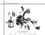
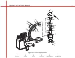
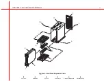
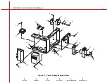
Figure 4.   Internal Cover Exploded View

1

2

3

4

5

14

13

12

11

10

6

7

9

8

Summary of Contents for OEC 9800 C-Arm

Page 1: ...OEC 9800 C Arm Illustrated Parts Manual 00 881712 02 Contents Installation Service Schematics Periodic Maintenance Illustrated Parts ...

Page 2: ...nd may not be reflected in this version of the document Contact GE OEC Technical Support for clarification if discrepancies arise OEC and OEC 9800 are registered trademarks of GE OEC Medical Systems Inc Other products and company names mentioned herein are the property of their respective owners The OEC 9800 C Arm is covered under one or more of the following U S and foreign patents 5 596 228 5 42...

Page 3: ...tions do not match the item numbers on the assembly drawings or the item numbers on the Bills of Materials Intended Audience This manual is intended for the properly trained engineer or technician who designs installs maintains or calibrates the Product Name Removing or installing parts should not be attempted by anyone who is not specifically trained by GE OEC Medical Systems Inc How to Use this ...

Page 4: ...ion Service Schematics Periodic Maintenance Illustrated Parts Manual Revision History Rev Dash Date Change Description A 01 September 1999 Manufacturing release B 02 December 1999 Added Super C and incorporated editorial changes C 02 February 2001 Format changes ...

Page 5: ...Collimator Exploded View 13 Figure 4 Internal Cover Parts List 14 Internal Cover Exploded View 15 Figure 5 Battery Power Parts List 16 Battery Power Panel Exploded View 17 Figure 6 Stator Capaitor Transformer Parts List 18 Stator Capaitor Transformer Exploded View 19 Figure 7 Power Panel Parts List 20 Power Panel Exploded View 21 Figure 8 Electronics Parts List 22 Electronics Exploded View 23 Figu...

Page 6: ...rts List 40 9 Flip Flop Exploded View 41 Figure 18 12 Flip Flop Parts List 42 12 Flip Flop Exploded View 43 Figure 19 Vertical Column Cross Arm Parts List 44 Vertical Column Cross Arm Exploded View 45 Figure 20 Cross Arm Brake Parts List 46 Cross Arm Brake Exploded View 47 Figure 21 Cross Arm Housing Mount Parts List 48 Cross Arm Housing Mount Exploded View 49 Figure 22 Cross Arm Brake Bearing Par...

Page 7: ...Figure 29 Rear Caster Parts List 64 Rear Caster Exploded View 65 Figure 30 Super C II Camera Parts List 1 of 2 66 Super C II Camera Exploded View 1 of 2 67 Figure 31 Super C II Camera Parts List 2 of 2 68 Super C II Camera Exploded View 2 of 2 69 Figure 32 Super C X Ray Tube Parts List 70 Super C X Ray Tube Exploded View 71 Figure 33 Super C Collimator Parts List 72 Super C Collimator Exploded Vie...

Page 8: ...1 Cover Front Right 1 9 12 313915 26 Screw NA Socket Hex 5 16 18 1 3 4 SBO 8 4 10 00 880897 01 End Cap Cross Beam 2 11 12 225160 06 Screw SEMS Spring Pan Torx 10x32 2 12 00 876038 01 Cover Cross Beam 1 13 13 311106 00 Nut Hex Lock External T 6 32 SST NA A 313 2 14 00 879830 01 Assembly Rear Cover 1 15 00 876692 02 Cover Label Back Door 1 16 12 311115 20 Screw NA Socket Hex 5 16 18 1 SZC 8 3 17 00 ...

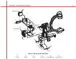
Page 9: ... 9800 C Arm Illustrated Parts Manual Contents Installation Service Schematics Periodic Maintenance Illustrated Parts Figure 1 Covers Exploded View 1 2 21 20 3 4 5 6 7 8 10 9 12 11 13 14 15 16 17 18 19 22 23 ...

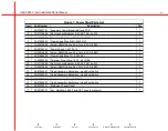
Page 10: ...crew NA Socket Hex 10 32 1 2 SST 3 11 12 225106 20 Screw SEMS Spring Pan Torx 6 32 1 SCZ 4 12 00 879126 01 Assembly CCD Camera 1K x 1K 9 1 12 00 879127 01 Assembly CCD Camera 1K x 1K 12 1 13 22 429863 00 Standoff Hex M F 1 4 20 3 250L SST 12 14 00 901226 02 Intensifier Image HX Rear Mount 9 1 14 00 901083 01 Intensifier Image HX Rear Mount 12 1 15 00 871303 01 Gasket X Ray Grid 1 16 00 901200 01 G...

Page 11: ...0 C Arm Illustrated Parts Manual Contents Installation Service Schematics Periodic Maintenance Illustrated Parts Figure 2 II Camera Exploded View 1 2 3 5 4 6 8 7 9 11 12 14 10 13 15 16 17 19 18 20 18 19 21 23 22 ...

Page 12: ...x 6 32 3 8 SZC 6 10 22 678482 00 Ring Retaining Internal Spl 2 312 SST 1 11 00 880838 01 Collimator Primary 9 Inch 1 12 00 880855 01 Spacer Foam primary Collimator 1 13 00 877286 01 Cover X Ray Tube 1 14 00 881519 01 Assembly X Ray Tube External Mount 1 15 00 901753 01 Assembly Thermal Switch not exploded for clarity 1 16 12 225160 10 Screw NA Socket Hex 10 32 5 8 SZC 2 17 00 875607 01 Cover High ...

Page 13: ...EC 9800 C Arm Illustrated Parts Manual Contents Installation Service Schematics Periodic Maintenance Illustrated Parts Figure 3 X Ray Tube Collimator Exploded View 1 2 3 4 5 6 7 8 10 11 12 13 14 9 17 16 15 ...

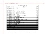
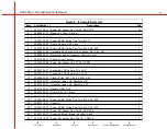
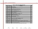
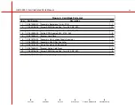
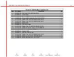
Page 14: ...8 08 Screw SEMS Spring Pan Torx 8 32 1 2 SZC 2 6 12 225106 08 Screw SEMS Spring Pan Torx 6 32 1 2 SZC 4 7 00 879694 01 Cover Front Card Rack 1 8 12 225108 08 Screw SEMS Spring Pan Torx 8 32 1 2 SZC 8 9 00 879992 01 Cover Component tray 1 10 14 181110 00 Washer Plain 10 SST MS15795 808 ID 221 1 11 12 225108 06 Screw SEMS Spring Pan Torx 8 32 3 8 SZC 1 12 12 225108 06 Screw SEMS Spring Pan Torx 8 32...

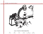
Page 15: ...15 OEC 9800 C Arm Illustrated Parts Manual Contents Installation Service Schematics Periodic Maintenance Illustrated Parts Figure 4 Internal Cover Exploded View 1 2 3 4 5 14 13 12 11 10 6 7 9 8 ...

Page 16: ...Transformer 1 3 12 225108 06 Screw SEMS Spring Pan Torx 8 32 3 8 SZC 4 4 00 879124 01 Assembly Power Panel 1 5 00 880519 01 Gasket Lemo Connector 1 6 12 225109 10 Screw SEMS Spring Pan Torx 8 32 5 8 SZC 4 7 00 879325 01 PCB Power Motor Relay 1 8 12 225108 06 Screw SEMS Spring Pan Torx 8 32 3 8 SZC 1 9 00 880406 02 Assembly Capacitor Power Module 1 10 00 900589 01 Battery Pack 1 11 00 875583 01 Ret...

Page 17: ...9800 C Arm Illustrated Parts Manual Contents Installation Service Schematics Periodic Maintenance Illustrated Parts Figure 5 Battery Power Panel Exploded View 1 2 See figure 6 3 4 See figure 7 5 6 7 9 8 11 10 ...

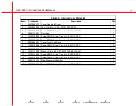
Page 18: ...1 Plate Multi Output Transformer 1 5 12 225108 08 Screw SEMS Spring Pan Torx 8 32 1 2 SZC 4 6 00 901148 02 Transformer Multi Output 1 7 12 225108 08 Screw SEMS Spring Pan Torx 8 32 1 2 SZC 1 8 41 599065 00 Capacitor AC Motor 40uF 330VAC 10 Terminals 1 9 41 599057 00 Capacitor AC Motor 30uF 240VAC Terminals 1 10 00 880759 01 Plate Capacitor Clamp 1 11 55 700477 00 Circuit Breaker 1A SPST 250VAC Pan...

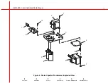
Page 19: ...19 OEC 9800 C Arm Illustrated Parts Manual Contents Installation Service Schematics Periodic Maintenance Illustrated Parts Figure 6 Stator Capaitor Transformer Exploded View 1 2 3 12 10 11 4 5 6 7 9 8 ...

Page 20: ...upply 5 12 15 1 7 12 225106 06 Screw SEMS Spring Pan Torx 6 32 3 8 SZC 1 8 22 012004 00 Clamp Cable Wire 1D 50W NYL 1 9 15 608092 00 Terminal Ring Crimp 16 14 6 LRB6 1 10 13 311106 00 Nut Hex Lock External 6 32 SST NA A 313 1 11 12 225106 06 Screw SEMS Spring Pan Torx 6 32 3 8 SZC 4 12 00 879455 01 Cable Assembly Backplane Hand Foot Switch 1 13 00 879455 01 Cable Assembly Backplane Hand Foot Switc...

Page 21: ...21 OEC 9800 C Arm Illustrated Parts Manual Contents Installation Service Schematics Periodic Maintenance Illustrated Parts Figure 7 Power Panel Exploded View 1 2 3 4 5 16 6 7 8 11 10 9 12 13 14 15 ...

Page 22: ...ock HLCL Spring 1 4 SST MS35338 2 10 14 121114 00 Washer Lock HLCL Spring 1 4 SST MS35338 2 11 12 331114 08 Screw NA Socket Hex 1 4 20 1 2 SZC 8 4 12 00 879782 01 Tray High Voltage Tank 1 13 12 255108 06 Screw SEMS Spring Pan Torx 8 32 3 8 SZC 4 14 00 879122 01 Assembly Generator Power Tray 1 15 12 225108 08 Screw SEMS Spring Pan Torx 8 32 1 2 SZC 5 16 00 879808 01 Bracket Cover Side 2 17 12 22510...

Page 23: ...d Parts Manual Contents Installation Service Schematics Periodic Maintenance Illustrated Parts Figure 8 Electronics Exploded View See figure 11 7 See figure 9 2 1 3 4 5 14 13 8 9 10 12 11 15 16 17 18 19 20 21 23 22 6 See figure10 ...

Page 24: ... 12 3 12 255106 06 Screw SEMS Spring Pan Torx 6 32 3 8 SZC 4 4 22 319804 00 Guide PCB Snapin 6 50L 31W 062 6 5 00 879696 01 Bracket Card Rack 2 6 00 878729 05 Assembly High Voltage Supply Regulator 1 7 00 879805 02 Assembly 486 X Ray Controller 1 8 00 879101 02 Fluoro Functions PCB Assembly 1 9 00 879696 01 Bracket Guide Card Rack 2 10 12 225106 06 Screw SEMS Spring Pan Torx 6 32 3 8 SZC 4 11 00 8...

Page 25: ...25 OEC 9800 C Arm Illustrated Parts Manual Contents Installation Service Schematics Periodic Maintenance Illustrated Parts Figure 9 Card Rack Exploded View 1 2 3 11 10 9 4 5 6 8 7 ...

Page 26: ...10 SST MS15795 808 ID 211 2 6 14 121110 00 Washer Plain 10 SST MS15795 808 ID 211 2 7 00 881324 01 Bracket EMI 1 8 00 900987 01 Tank High Voltage 1 9 14 121114 00 Washer Plain 1 4 SST MS15795 810 ID 276 1 10 14 211114 00 Washer Lock HLCL Spring 1 4 SST MS35338 1 11 13 111114 00 Nut Hex 1 4 20 SST MS51971 1 1 12 00 901404 01 Insulator IGBT 2 13 00 880405 01 Assembly IGBT Snubber 1 14 14 121110 00 W...

Page 27: ...7 OEC 9800 C Arm Illustrated Parts Manual Contents Installation Service Schematics Periodic Maintenance Illustrated Parts Figure 10 IGBT Snubber Tank Exploded View 1 2 3 16 15 14 13 12 4 5 6 7 8 9 10 11 ...

Page 28: ...1 Chassis Component 1 8 13 311108 00 Nut Hex Lock External T 8 32 SST NA A 344 3 9 12 225106 08 Screw SEMS Spring Pan Torx 6 32 1 2 SZC 10 10 00 879784 01 Bracket Component Clamp 1 11 41 718504 00 Capacitor Polypropylene 2uF 600 V 10 Terminals 4 12 00 879785 01 Cover Component Clamp 1 13 22 012002 00 Clamp Cable Wire 5 8D 50W Nylon 1 14 00 901177 01 Power Supply 24VDC 1 15 00 879674 01 Assembly Po...

Page 29: ...00 C Arm Illustrated Parts Manual Contents Installation Service Schematics Periodic Maintenance Illustrated Parts Figure 11 Power Supply Exploded View 1 2 3 4 5 6 7 8 9 10 2 11 12 2 13 2 14 9 15 9 2 16 17 19 18 ...

Page 30: ... Cross Arm 1 6 00 879502 02 Assembly Control Panel Left 1 7 12 215006 06 Screw Machine Flanged Torx 6 32 3 8 SZC 8 8 12 225104 05 Screw SENS Spring Pan Torx 4 40 5 16 SZC 6 9 00 880324 01 PCB Control Panel Processor I O 1 10 00 878488 03 Assembly Control Panel Processor 1 11 00 880821 01 Assembly L Arm Mechanical 1 12 00 880655 01 Flip Flop 9 Inch 1 13 00 880656 01 Flip Flop 12 Inch 1 14 12 311114...

Page 31: ...s Manual Contents Installation Service Schematics Periodic Maintenance Illustrated Parts Figure 12 Control Panel L Arm Exploded View See figure 13 See figures 15 16 See figures See figure 14 1 5 6 7 8 9 10 15 14 11 12 13 17 18 16 2 3 4 ...

Page 32: ...umber Description Qty 1 00 901403 01 Vacuum Fluorescent Display Module SCD 1 2 00 880843 01 Lens Cross Arm Cover 1 3 00 901151 01 Panel Assembly Cont 9800 C Arm 1 4 00 880842 01 Cover Side Cross Arm 1 5 00 879407 01 Cable Assembly Fast Stop 1 6 12 225104 06 Screw SENS Spring Pan Torx 4 40 3 8 SZC 10 Figure 13 Control Panel Parts List ...

Page 33: ...33 OEC 9800 C Arm Illustrated Parts Manual Contents Installation Service Schematics Periodic Maintenance Illustrated Parts Figure 13 Control Panel Exploded View 1 2 3 4 5 6 ...

Page 34: ...775ID 6600WD 1 9 21 301785 00 Nut Lock Brg 1 378 BRG 1 906OD Steel Zinc 1 10 00 880704 01 Cover Plate Access L Arm 1 11 00 880778 01 Handle Lower L Arm 1 12 12 311114 24 Screw NA Socket Hex 1 4 20 1 1 2 SZC 8 3 13 14 901029 00 Washer Flange 7 16 Steel N A ID 469 OD 927 1 14 12 901004 22 Screw NA Socket Hex 7 16 20 1 1 4 SZC 8 1 15 20 843001 00 Rod End Spherical Bearing M RH 4375ID 1 16 13 161167 0...

Page 35: ...trated Parts Manual Contents Installation Service Schematics Periodic Maintenance Illustrated Parts Figure 14 L Arm Exploded View 1of 3 See figures 15 16 1 17 18 5 6 See figures 2 3 4 7 8 9 10 12 11 13 14 15 16 17 18 19 20 21 ...

Page 36: ...9 01 Stop Slider L Arm 1 8 88 299477 00 Lub grease GP 14 1OZ CRTG AR 9 00 880705 01 Weldment Shaft Cross Arm 1 10 00 880696 01 Cover Ring L Arm 1 11 00 881233 02 Label Horizontal Cross Arm 1 12 00 879905 01 Machining Cross Arm 1 13 00 881233 01 Label Horizontal Cross Arm 1 14 19 224948 00 Pin Spring 438OD 2 50 Steel 2 15 19 224771 00 Pin Spring 3750OD 750 SZC 2 16 21 301785 00 Nut Lock Brg 1 378 B...

Page 37: ...d Parts Manual Contents Installation Service Schematics Periodic Maintenance Illustrated Parts Figure 15 L Arm Exploded View 2 of 3 19 See figure 16 See figure 16 See figure 16 20 18 4 17 1 2 16 3 6 4 5 15 4 6 7 8 9 10 11 12 13 14 ...

Page 38: ...e L Arm 1 7 21 301785 00 Nut Lock Brg 1 378 Brg 1 906OD Steel Zinc 10 8 27 402277 00 O Ring 549ID X 103WD NPRN 113 3 9 00 879394 02 Insert Handle 3 10 12 225160 08 Screw SEMS Spring Pan Torx 10 32 1 2 SZC 4 11 00 876981 01 Handle Brake Flip Flop 4 12 22 678622 00 Ring Retaining External basic 7 16 Spring Steel 4 13 00 879344 01 Actuator Right Hand 2 14 00 880701 01 Screw Adjust Spherical L Arm 1 1...

Page 39: ...s Manual Contents Installation Service Schematics Periodic Maintenance Illustrated Parts Figure 16 L Arm Exploded View 3 of 3 1 2 3 4 18 5 17 6 7 8 7 9 10 12 13 7 8 7 9 10 11 12 16 7 11 14 8 7 9 11 10 12 13 7 15 7 5 8 7 9 16 7 12 11 10 ...

Page 40: ...88 299282 00 Adhesive Slt Blue Bottle 10cc 242 21 10 11 00 881222 01 Spring Roller 1 12 14 999724 00 Washer Pl 3 8 Nylon NA ID 375 OD 750 2 13 00 880385 01 Pivot Brake 1 14 12 225106 06 Screw SEMS Spring Pan Torx 6 32 3 8 SZC 2 15 00 876704 01 Handle Brake C Rotation 1 16 00 880383 01 Shaft Brake 1 17 00 880384 01 Cam Brake 1 18 88 299477 00 Lub Grease GP 14 1OZ CRTG AR 19 21 180020 00 Bearing Cyl...

Page 41: ... Parts Manual Contents Installation Service Schematics Periodic Maintenance Illustrated Parts Figure 17 9 Flip Flop Exploded View 25 2 3 1 22 4 5 6 7 8 9 10 11 2 3 21 10 20 3 12 20 3 19 17 18 16 2 3 15 14 13 23 18 23 18 14 15 19 24 ...

Page 42: ...82 00 Adhesive Slt Blue Bottle 10cc 242 21 10 11 00 881222 01 Spring Roller 1 12 14 999724 00 Washer Panel 3 8 Nylon NA ID 375 OD 750 2 13 00 880385 01 Pivot Brake 1 14 12 225106 06 Screw SEMS Spring Pan Torx 6 32 3 8 SZC 2 15 00 876704 01 Handle Brake C Rotation 2 16 00 880383 01 Shaft Brake 1 17 00 880384 01 Cam Brake 1 18 88 299477 00 Lub Grease Gp 14 10oz CRTG 4 19 21 180020 00 Bearing Cylinde...

Page 43: ...Parts Manual Contents Installation Service Schematics Periodic Maintenance Illustrated Parts Figure 18 12 Flip Flop Exploded View 25 1 2 3 4 5 6 7 8 2 3 9 10 11 12 20 3 22 21 10 20 3 2 3 16 15 14 17 18 19 23 18 14 15 24 23 18 19 13 ...

Page 44: ...er 1 8 00 881546 01 Spacer Shield 1 9 12 311114 14 Screw NA Socket Hex 1 4 20 7 8 SZC 8 2 10 12 318069 26 Screw Metric Socket Hex M10X1 5 40MM SZC 4 11 14 141116 00 Washer Pl 3 8 SZC NA ID 437 OD 1 000 4 12 00 879796 02 Base Machining 1 13 00 901166 01 Column Lift SCD 1 14 00 879809 01 Plate Cover Rear 1 15 12 318069 26 Screw Metric Socket Hex M10X1 5 40MM SZC 2 16 00 879828 01 Gasket Column Verti...

Page 45: ...rvice Schematics Periodic Maintenance Illustrated Parts Figure 19 Vertical Column Cross Arm Exploded View See figure 24 See figure 26 See figure 27 See figures 28 29 See figure 20 See figures 21 22 23 1 2 3 4 5 6 7 8 9 16 17 18 19 20 21 15 14 13 11 10 12 See figure 25 ...

Page 46: ...andle Brake Cross Arm 1 7 14 121106 00 Washer Pl 6 SST MS15795 805 ID 151 1 8 12 322006 20 Screw Locking Socket Hex 6 32 1 SST 1 9 00 879678 01 Shaft Brake Cross Arm 1 10 88 299477 00 Lub Grease Gp 14 1OZ CRTG 2 11 19 224754 00 Pin Spring 125OD 1 SST 1 12 00 879676 01 Bushing Cross Arm 2 13 88 299199 00 Adhesive Green 50CC 605 31 2 14 19 224763 00 Pin Spring 125OD 500 SST 1 15 19 224770 00 Pin Spr...

Page 47: ...9800 C Arm Illustrated Parts Manual Contents Installation Service Schematics Periodic Maintenance Illustrated Parts Figure 20 Cross Arm Brake Exploded View 18 1 2 17 16 10 3 4 15 14 5 6 7 8 9 10 11 12 13 12 13 ...

Page 48: ...Socket Hex 3 8 16 3 4 SZC 8 1 6 88 299282 00 Adhesive Slt Blue Bottle 10cc 242 21 1 7 12 311116 22 Screw NA Socket Hex 1 8 16 1 1 4 SZC 8 1 8 00 879797 01 Shaft Mount Cross Arm 1 9 21 119948 00 Bearing Roller Taper Cone 2 0000ID 8750WD 1 10 88 299477 00 Lub Grease Gp 14 10Oz CRTG 2 11 21 119949 00 Bearing Roller Taper Cone 3 2500ID 6500WD 1 12 19 221927 00 Pin Dowel 2503OD 740 Steel 2 13 00 879702...

Page 49: ...9800 C Arm Illustrated Parts Manual Contents Installation Service Schematics Periodic Maintenance Illustrated Parts Figure 21 Cross Arm Housing Mount Exploded View 2 3 1 4 5 6 7 6 9 10 11 8 12 13 11 9 10 14 15 ...

Page 50: ... 1 5 88 299282 00 Adhesive Slt Blue Bottle 10cc 242 21 5 6 12 311114 08 Screw NA Socket Hex 1 4 20 1 2 SZC 8 1 7 88 299282 00 Adhesive Slt Blue Bottle 10cc 242 21 4 8 00 879707 01 Assembly Brake Pad 1 9 00 879703 01 Plate Floating 1 10 27 409210 00 O Ring 614ID X 070WD 016 1 11 88 299477 00 Lub Grease GP 14 1OZ CRTG 1 12 00 879704 01 Actuator Brake 1 13 88 299477 00 Lub Grease GP 14 1OZ CRTG 1 14 ...

Page 51: ...atics Periodic Maintenance Illustrated Parts Figure 22 Cross Arm Brake Bearing Exploded View See figure 23 Detail A Detail B See figure 23 See figure 23 Detail C See figure 23 Detail A Detail B See figure 23 See figure 23 Detail C 1 2 3 4 5 6 7 8 9 10 11 12 13 14 15 4 5 1 2 3 2 3 ...

Page 52: ...ted Parts Item Part Number Description Qty 1 22 680004 00 Ring Retaining External E Type 3 4 Spring Steel 28 2 00 880529 01 Roller Cross Arm Narrow 16 3 00 879893 01 Shaft Roller Cross Arm 6 4 23 109950 00 Bearing BA 6693ID 1 3780OD 3937WD 8 5 00 879894 01 Roller Cross Arm 2 Figure 23 Cross Arm Bearings Parts List ...

Page 53: ...llustrated Parts Manual Contents Installation Service Schematics Periodic Maintenance Illustrated Parts Figure 23 Cross Arm Bearings Exploded View Detail A 2 Places 1 2 3 1 4 5 3 1 4 3 Detail C 2 Places Detail B 2 Places ...

Page 54: ...504OD 3543WD 1 7 00 879027 01 Shaft Tiller Short Steering 1 8 21 109947 00 Bearing call 625ID 1 375OD 4375WD 1 9 00 878942 01 Sprocket Drive Steering 1 10 19 224945 00 Pin Spring 250OD 1 SZC 1 11 14 900012 00 Washer Plain 10 SZC NA ID 219 OD 500 6 12 14 211110 00 Washer Lock Helical Spring 10 SZC NA ID 194 3 13 12 311110 12 Screw NA Socket Hex 10 24 3 4 SZC 8 3 14 00 878945 01 Cam Detent Steering ...

Page 55: ...C 9800 C Arm Illustrated Parts Manual Contents Installation Service Schematics Periodic Maintenance Illustrated Parts Figure 24 Rear Steering Exploded View 1 of 2 1 2 3 4 5 6 7 8 9 10 11 12 13 14 15 16 18 17 ...

Page 56: ...ssis 1 10 21 128919 00 Bearing Thrust Washer 500ID 8750OD 0585WD 4 11 21 128814 00 Bearing Needle Roller 500ID 750OD 750WD 2 12 00 878943 01 Sprocket Idler Steering 2 13 12 999545 00 Screw NA Shoulder Hex 3 8 16 1 2X1 1 4 2 14 21 139743 00 Bearing Cylindrical Flanged 375ID 502OD 1 000L 1 15 12 999539 00 Screw NA Shoulder Hex 5 16 18 3 8X1 1 4 1 16 13 111114 00 Nut Hex 1 4 20 Stainless Steel MS5197...

Page 57: ... C Arm Illustrated Parts Manual Contents Installation Service Schematics Periodic Maintenance Illustrated Parts Figure 25 Rear Steering Exploded View 2 of 2 1 2 3 4 5 9 6 7 8 10 11 12 13 14 15 16 17 22 21 20 19 18 ...

Page 58: ... 2 00 879116 01 Support Bearing Brake Rod Flat 2 3 21 139774 00 Bearing Cylindrical Flanged 625ID 750OD 500L 4 4 00 879013 01 Support Bearing Brake Rod Steering 2 5 00 876586 02 Shaft Actuator Rear Caster 1 6 12 363914 22 Screw NA Button Hex 1 4 20 1 1 4 SBO 2 7 00 879012 01 Cam Brake 2 8 12 311114 14 Screw NA Socket Hex 1 4 20 7 8 SZC 8 6 9 00 876833 03 Pedal Rear Wheel Brake 2 Figure 26 Rear Bra...

Page 59: ...59 OEC 9800 C Arm Illustrated Parts Manual Contents Installation Service Schematics Periodic Maintenance Illustrated Parts Figure 26 Rear Brake Exploded View 1 2 1 3 4 5 6 7 8 9 3 ...

Page 60: ...8450 00 Ring Retaining Internal Basic 1 3 8 Spring Steel 2 5 21 109912 00 Bearing Ball Double 5906ID 1 3780ID 625WD 2 6 22 678620 00 Ring Retaining External 5100 59S 2 7 12 331116 32 Screw NA Flat Hex 3 8 16 2 1 4 SZC 8 2 8 00 881347 01 Blade Cable Pusher Front 2 9 12 225106 10 Screw SEMS Spring Pan Torx 6 32 5 8 SZC 4 10 21 259986 00 Caster Wheel 4 inch Diameter 1 3 8 inch Wide 2 11 00 881295 01 ...

Page 61: ...61 OEC 9800 C Arm Illustrated Parts Manual Contents Installation Service Schematics Periodic Maintenance Illustrated Parts Figure 27 Front Caster Exploded View 1 2 3 4 5 6 11 10 9 8 7 12 ...

Page 62: ... Spring Cl 375PD Steel 4 3 00 879147 01 Turnbuckle Chain Left Hand 2 4 00 879146 01 Turnbuckle Chain Right Hand 2 5 00 878953 01 Chain Steering Long 1 6 00 879145 01 Turnbuckle Chain Body 2 7 00 880889 01 Assembly Rear Wheel 2 8 00 881587 01 Assembly Skirt Cable Pusher 2 9 12 225108 08 Screw SEMS Spring Pan Torx 8 32 1 2 SZC 16 10 00 881346 01 Blade Cable Pusher Rear 4 Figure 28 Steering Chain Cab...

Page 63: ...EC 9800 C Arm Illustrated Parts Manual Contents Installation Service Schematics Periodic Maintenance Illustrated Parts Figure 28 Steering Chain Cable Pusher Exploded View 1 2 3 4 5 6 7 8 9 10 See figure 29 ...

Page 64: ...pring Compression 720OD 1 250LG 072WD Steel 1 9 21 139776 00 Bearing Cylinder Flange 500ID 625OD 750L 1 10 12 333968 40 Screw NA Fl Hex 1 2 20 3 SBO 8 1 11 88 299282 00 Adhesive SLT Blue Bottle 10cc 242 21 AR 12 00 901077 01 Wheel Plastic 8 Inch Steering 1 13 00 880888 02 Yoke Wheel Rear 1 14 21 139777 00 Bearing Cylinder Fl 875ID 1 000OD 750L 1 15 00 878944 01 Sprocket Yoke Steering 1 16 22 11992...

Page 65: ...EC 9800 C Arm Illustrated Parts Manual Contents Installation Service Schematics Periodic Maintenance Illustrated Parts Figure 29 Rear Caster Exploded View 1 2 3 4 5 7 6 8 9 10 11 12 13 14 15 16 17 18 19 20 ...

Page 66: ...C 8 4 3 00 881075 01 Handle C 1 4 00 881023 01 End Cap Machining 1 5 00 880833 01 Weight Rear Top 2 6 00 877033 02 Pad Bumper Flip Flop 1 7 00 877033 01 Pad Bumper Flip Flop 1 8 00 881023 01 End Cap Machining 1 9 12 311114 08 Screw NA SKT HEX 1 4 20 1 2 SZC 8 4 10 00 880834 01 Weight Front Top 2 11 12 225108 12 Screw SEMS SPR PAN TRX 8 32 3 4 SZC 4 12 00 879488 02 Weldment C Arm C Major 1 Figure 3...

Page 67: ...800 C Arm Illustrated Parts Manual Contents Installation Service Schematics Periodic Maintenance Illustrated Parts Figure 30 Super C II Camera Exploded View 1 of 2 See Figure 31 11 12 3 11 2 1 9 8 7 6 5 10 4 3 ...

Page 68: ... TRX 6 32 1 SZC 6 8 00 901200 01 Grid X Ray 10 1 9 Inch 1 9 00 901226 02 Intensifer Image HX Rear 1 10 12 225106 08 Screw SEMS SPR PAN TRX 6 32 1 2 SZC 4 11 14 146006 00 Washer Shim NA ID 0202 OD 625 063 4 12 12 225106 04 Screw SEMS SPR PAN TRX 6 32 1 4 SZC 8 13 00 880688 01 Weldment Mount Connector Camera Cover 1 14 00 879486 01 Top Camera II Machining 2 15 12 225106 04 Screw SEMS SPR PAN TRX 6 3...

Page 69: ...0 C Arm Illustrated Parts Manual Contents Installation Service Schematics Periodic Maintenance Illustrated Parts Figure 31 Super C II Camera Exploded View 2 of 2 14 8 9 6 15 16 13 12 11 10 18 17 19 20 1 5 4 3 2 7 ...

Page 70: ...al Spl 2 312 SST 1 7 00 880838 01 Collimator Primary 9 Inch 1 8 00 880855 01 Spacer Foam primary Collimator 1 9 00 877286 01 Cover X Ray Tube 1 10 00 881519 01 Assembly X Ray Tube External Mount 1 11 00 877946 01 Retainer Plug HV 2 12 00 877947 01 Nut X Ray Hi Volt 2 13 00 881970 01 Asm Collimator Super C Integrated 1 14 12 311160 06 Screw Sockethead Hex 10 32 3 8 SZC 2 15 00 880881 01 Heat Sink 1...

Page 71: ...00 C Arm Illustrated Parts Manual Contents Installation Service Schematics Periodic Maintenance Illustrated Parts Figure 32 Super C X Ray Tube Exploded View See Figure 33 1 16 5 7 8 6 10 9 4 5 11 12 15 14 13 3 2 ...

Page 72: ...h 1 4 12 311114 12 Screw Sockethead Hex 1 4 20 3 4 SZC 1 5 12 225106 06 Screw SEMS Spring Pan Torx 6 32 3 8 SZC 1 6 12 215060 08 Screw Machine Flathead Torx 10 32 1 2 SZC 2 7 12 312060 30 Screw Sockethead Hex 10 32 2 SST 4 8 14 121110 00 Washer Plain 10 SST 4 9 00 881105 01 Weight Top X Ray 1 10 00 881106 01 Weight Front X Ray 1 11 12 225160 08 Screw SEMS Spring Panhead Torx 10 32 1 2 SZC 2 12 00 ...

Page 73: ...73 OEC 9800 C Arm Illustrated Parts Manual Contents Installation Service Schematics Periodic Maintenance Illustrated Parts Figure 33 Super C Collimator Exploded View 11 12 13 4 5 7 8 10 6 2 3 1 9 8 7 ...

Page 74: ...1 Shaft Pivot Super C 1 12 21 119936 00 Bearing Roller Tapered Cone 3 000 ID 5313 WD 1 13 21 119937 00 Bearing Roller Tapered Cup 4 1563 OD 3750 WD 1 14 00 880820 01 Assembly Brake Shoe 1 15 00 879955 01 Spacing Housing Rear C Major 1 16 00 880890 01 Plate Stop Flip Flop 380 1 17 00 880840 01 Shaft Brake Flip Flop 1 18 00 879344 01 Actuator Right Handle 9800 1 19 21 119921 00 Bearing Roller Tapere...

Page 75: ...m Illustrated Parts Manual Contents Installation Service Schematics Periodic Maintenance Illustrated Parts Figure 34 Super C L Arm Exploded View 1 2 3 4 5 6 7 8 9 10 11 12 13 14 15 16 17 4 18 6 9 7 19 20 21 22 23 24 8 ...

Page 76: ...dhesive Slt Blue Bottle 10cc 242 21 AR 11 00 881222 01 Spring Roller 1 12 14 999724 00 Washer Plain 3 8 Nylon NA ID 375 OD 750 2 13 00 880385 01 Pivot Brake 1 14 12 225106 06 Screw SEMS Spring Pan Torx 6 32 3 8 SZC 2 15 00 876704 01 Handle Brake C Rotation 2 16 00 880383 01 Shaft Brake 1 17 00 880384 01 Cam Brake 1 18 88 299477 00 Lub Grease Gp 14 10oz CRTG AR 19 21 180020 00 Bearing Cylinder 375I...

Page 77: ...rts Manual Contents Installation Service Schematics Periodic Maintenance Illustrated Parts Figure 35 Super C Flip Flop Exploded View 1 2 3 4 5 6 7 8 9 10 2 3 11 21 10 20 3 24 12 13 14 15 16 2 3 17 18 19 19 15 14 23 18 23 18 22 25 20 3 ...

Reviews: