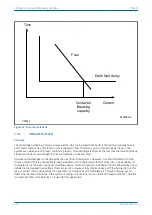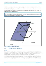
such overvoltages is not too costly. Higher system voltages would normally be solidly earthed or earthed using a
low impedance.
A special case of high impedance earthing using a reactor occurs when the inductive earthing reactance is made
equal to the total system capacitive reactance to earth at system frequency. This practice is widely referred to as
Petersen (or resonant) Coil Earthing. With a correctly tuned system, the steady state earthfault current is zero, so
that earth faults become self-extinguishing. Such systems can, if designed, be run with one phase earthed for a
long period until the cause of the fault is identified and rectified. With the effectiveness of this method being
dependent on the correct tuning of the coil reactance to the system capacitive reactance, an expansion of the
system at any time would necessitate an adjustment of the coil reactance.
Petersen coil earthed systems are commonly found in areas where the power system consists mainly of rural
overhead lines and can be particularly beneficial in locations which are subject to a high incidence of transient
faults. The Petersen coil, for example, can extinguish transient earth faults caused by lightning strikes without the
need for outages.
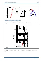
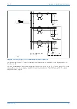
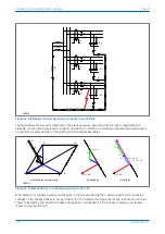
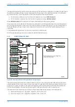
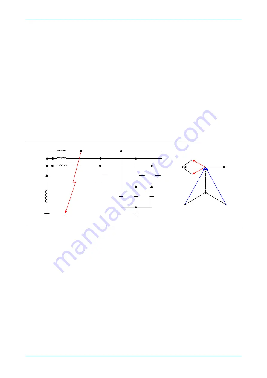
The figure below shows a source of generation earthed through a Petersen Coil, with an earth fault applied on the
A Phase. Under this situation you can see that the A phase shunt capacitance becomes short circuited by the fault.
Therefore, the calculations show that if the reactance of the earthing coil is set correctly, the resulting earth fault
current is zero.
V00631
jX
L
AN
L
V
jX
AB
C
V
jX
ac
C
V
jX
0
AN
f
B
C
L
AN
B
C
L
V
I
I
I
jX
V
if
I
I
jX
Source
Petersen
Coil
Current vectors for A phase fault
I
f
-I
C
A
B
C
N
-I
B
I
L
V
AB
V
AC
-I
B
-I
C
(=I
L
)
(=-I
B
)
(=-I
C
)
-jX
C
-jX
C
-jX
C
Figure 51: Current distribution in Petersen coil earthed system
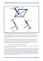
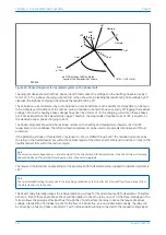
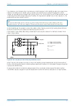
Prior to actually applying protective relays to provide earth fault protection on systems which are earthed using a
Petersen Coil, it is imperative to gain an understanding of the current distributions that occur under fault
conditions on such systems. With this information you can decide on the type of relay that may be applied,
ensuring that it is both set and connected correctly.
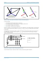
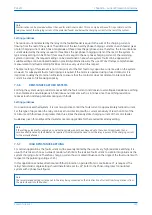
The figure below shows a radial distribution system having a source which is earthed using a Petersen Coil. Three
outgoing feeders are present, the lower of which has a phase to earth fault applied on the C phase.
P24xM
Chapter 6 - Current Protection Functions
P24xM-TM-EN-2.1
125
Summary of Contents for P24DM
Page 2: ......
Page 17: ...Appendix C Wiring Diagrams 467 P24xM Contents P24xM TM EN 2 1 xv...
Page 18: ...Contents P24xM xvi P24xM TM EN 2 1...
Page 24: ...Table of Figures P24xM xxii P24xM TM EN 2 1...
Page 25: ...CHAPTER 1 INTRODUCTION...
Page 26: ...Chapter 1 Introduction P24xM 2 P24xM TM EN 2 1...
Page 37: ...CHAPTER 2 SAFETY INFORMATION...
Page 38: ...Chapter 2 Safety Information P24xM 14 P24xM TM EN 2 1...
Page 51: ...CHAPTER 3 HARDWARE DESIGN...
Page 52: ...Chapter 3 Hardware Design P24xM 28 P24xM TM EN 2 1...
Page 66: ...Chapter 3 Hardware Design P24xM 42 P24xM TM EN 2 1...
Page 67: ...CHAPTER 4 SOFTWARE DESIGN...
Page 68: ...Chapter 4 Software Design P24xM 44 P24xM TM EN 2 1...
Page 77: ...CHAPTER 5 CONFIGURATION...
Page 78: ...Chapter 5 Configuration P24xM 54 P24xM TM EN 2 1...
Page 94: ...Chapter 5 Configuration P24xM 70 P24xM TM EN 2 1...
Page 95: ...CHAPTER 6 CURRENT PROTECTION FUNCTIONS...
Page 96: ...Chapter 6 Current Protection Functions P24xM 72 P24xM TM EN 2 1...
Page 188: ...Chapter 6 Current Protection Functions P24xM 164 P24xM TM EN 2 1...
Page 189: ...CHAPTER 7 RESTRICTED EARTH FAULT PROTECTION...
Page 190: ...Chapter 7 Restricted Earth Fault Protection P24xM 166 P24xM TM EN 2 1...
Page 201: ...CHAPTER 8 CB FAIL PROTECTION...
Page 202: ...Chapter 8 CB Fail Protection P24xM 178 P24xM TM EN 2 1...
Page 215: ...CHAPTER 9 CURRENT TRANSFORMER REQUIREMENTS...
Page 216: ...Chapter 9 Current Transformer Requirements P24xM 192 P24xM TM EN 2 1...
Page 224: ...Chapter 9 Current Transformer Requirements P24xM 200 P24xM TM EN 2 1...
Page 225: ...CHAPTER 10 VOLTAGE PROTECTION FUNCTIONS...
Page 226: ...Chapter 10 Voltage Protection Functions P24xM 202 P24xM TM EN 2 1...
Page 245: ...CHAPTER 11 FREQUENCY PROTECTION FUNCTIONS...
Page 246: ...Chapter 11 Frequency Protection Functions P24xM 222 P24xM TM EN 2 1...
Page 261: ...CHAPTER 12 POWER PROTECTION FUNCTIONS...
Page 262: ...Chapter 12 Power Protection Functions P24xM 238 P24xM TM EN 2 1...
Page 265: ...CHAPTER 13 MONITORING AND CONTROL...
Page 266: ...Chapter 13 Monitoring and Control P24xM 242 P24xM TM EN 2 1...
Page 294: ...Chapter 13 Monitoring and Control P24xM 270 P24xM TM EN 2 1...
Page 295: ...CHAPTER 14 SUPERVISION...
Page 296: ...Chapter 14 Supervision P24xM 272 P24xM TM EN 2 1...
Page 312: ...Chapter 14 Supervision P24xM 288 P24xM TM EN 2 1...
Page 313: ...CHAPTER 15 DIGITAL I O AND PSL CONFIGURATION...
Page 314: ...Chapter 15 Digital I O and PSL Configuration P24xM 290 P24xM TM EN 2 1...
Page 327: ...CHAPTER 16 COMMUNICATIONS...
Page 328: ...Chapter 16 Communications P24xM 304 P24xM TM EN 2 1...
Page 386: ...Chapter 16 Communications P24xM 362 P24xM TM EN 2 1...
Page 387: ...CHAPTER 17 CYBER SECURITY...
Page 388: ...Chapter 17 Cyber Security P24xM 364 P24xM TM EN 2 1...
Page 405: ...CHAPTER 18 INSTALLATION...
Page 406: ...Chapter 18 Installation P24xM 382 P24xM TM EN 2 1...
Page 419: ...CHAPTER 19 COMMISSIONING INSTRUCTIONS...
Page 420: ...Chapter 19 Commissioning Instructions P24xM 396 P24xM TM EN 2 1...
Page 443: ...CHAPTER 20 MAINTENANCE AND TROUBLESHOOTING...
Page 444: ...Chapter 20 Maintenance and Troubleshooting P24xM 420 P24xM TM EN 2 1...
Page 453: ...CHAPTER 21 TECHNICAL SPECIFICATIONS...
Page 454: ...Chapter 21 Technical Specifications P24xM 430 P24xM TM EN 2 1...
Page 486: ...Chapter 21 Technical Specifications P24xM 462 P24xM TM EN 2 1...
Page 487: ...APPENDIX A ORDERING OPTIONS...
Page 488: ...Appendix A Ordering Options P24xM 464 P24xM TM EN 2 1...
Page 491: ...APPENDIX B SETTINGS AND SIGNALS...
Page 493: ...APPENDIX C WIRING DIAGRAMS...
Page 494: ...Appendix C Wiring Diagrams P24xM 468 P24xM TM EN 2 1...
Page 497: ......
Page 498: ......
Page 499: ......
Page 500: ......
Page 501: ......
Page 502: ......
Page 503: ......
Page 504: ......
Page 505: ......
Page 506: ......
Page 507: ......
Page 508: ......
Page 509: ......
Page 510: ......
Page 511: ......
Page 512: ......
Page 513: ......
Page 514: ......
Page 515: ......
Page 516: ......
Page 517: ......
Page 518: ......
Page 519: ......
Page 520: ......
Page 521: ......
Page 522: ......
Page 523: ......
Page 524: ......
Page 525: ......
Page 526: ......
Page 527: ......
Page 528: ......
Page 529: ......
Page 530: ......
Page 531: ......
Page 532: ......
Page 533: ......
Page 534: ......
Page 535: ......
Page 536: ......
Page 537: ......
Page 538: ......
Page 539: ......
Page 540: ......
Page 541: ......
Page 542: ......
Page 543: ......
Page 544: ......
Page 545: ......
Page 546: ......
Page 547: ......
Page 548: ......
Page 549: ......
Page 550: ......
Page 551: ......
Page 552: ......
Page 553: ......
Page 554: ......
Page 555: ......
Page 556: ......
Page 557: ......
Page 558: ......
Page 559: ......
Page 560: ......
Page 561: ......
Page 562: ......
Page 563: ......
Page 564: ......
Page 565: ......
Page 566: ......
Page 567: ......
Page 568: ......
Page 569: ......
Page 570: ......
Page 571: ......
Page 572: ......
Page 573: ......
Page 574: ......
Page 575: ......
Page 576: ......
Page 577: ......
Page 578: ......
Page 579: ......
Page 580: ......
Page 581: ......
Page 582: ......
Page 583: ......
Page 584: ......
Page 585: ......
Page 586: ......
Page 587: ......
Page 588: ......
Page 589: ......
Page 590: ......
Page 591: ......
Page 592: ......
Page 593: ......
Page 594: ......
Page 595: ......
Page 596: ......
Page 597: ......
Page 598: ......
Page 599: ......

