Appendix B - Settings and Signals
P54A/B/C/E
B246
P54xMED-TM-EN-1
ORDINAL
SIGNAL NAME
ELEMENT NAME
DESCRIPTION
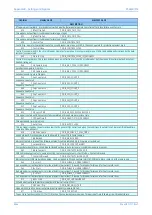
VT supervision slow block - blocks elements which would otherwise maloperate some time after a fuse failure event occurs
834
Bfail1 Trip 3ph
DDB_CBF1_TRIP_3PH
Three phase output from circuit breaker failure logic, stage 1
835
Bfail2 Trip 3ph
DDB_CBF2_TRIP_3PH
Three phase output from circuit breaker failure logic, stage 2
838
Control Trip
DDB_CONTROL_TRIP
Control trip - operator trip instruction to the circuit breaker, via menu, or SCADA. (Does not operate for protection element trips)
839
Control Close
DDB_CONTROL_CLOSE
Control close command to the circuit breaker. Operates for a manual close command (menu, SCADA), and additionally is driven by the auto-
reclose close command
842
Close in Prog
DDB_CONTROL_CLOSE_IN_PROGRESS
Control close in progress - the relay has been given an instruction to close the circuit breaker, but the manual close timer delay has not yet
finished timing out
844
AR 3pole in prog
DDB_AR_3_POLE_IN_PROGRESS
Auto Reclose 3 pole in Progress
845
AR 1pole in prog
DDB_AR_1_POLE_IN_PROGRESS
Auto Reclose AR 1 pole in Progress
846
Seq Counter = 0
DDB_SEQ_COUNT_0
Sequence Counter = 0
847
Seq Counter = 1
DDB_SEQ_COUNT_1
Sequence Counter = 1
848
Seq Counter = 2
DDB_SEQ_COUNT_2
Sequence Counter = 2
849
Seq Counter = 3
DDB_SEQ_COUNT_3
Sequence Counter = 3
850
Seq Counter = 4
DDB_SEQ_COUNT_4
Sequence Counter = 4
851
Seq Counter > 4
DDB_SEQ_COUNT_5
Sequence Counter > 4
852
CB Succ 3P AR
DDB_AR_SUCCESSFUL_RECLOSE
This signal is set when CB has successfully completed a three phase autoreclose cycle.
853
3P Dead Time IP
DDB_DEAD_TIME_IN_PROGRESS
Three pole dead time in progress
854
Auto Close
DDB_AUTO_CLOSE
This is a signal issued by the autoreclose logic to the general CB Control logic when the conditions to autoreclose CB are satisfied (dead time
complete, CB healthy etc).
858
AR Force 3 pole
DDB_AR_FORCE_3_POLE_TRIPS
Used by in-built Trip conversion logic to allow AR to convert CB to 3pole tripping
859
AR Blocked
DDB_AR_BLOCKED
Indicates that AR is in one of the following states, Disabled, Inhibited, AR In Progress or Locked out
860
Lockout Alarm
DDB_CB_LOCKOUT_ALARM
Composite lockout alarm - circuit breaker locked out due to auto-recloser, or condition monitoring reasons
862
Block Contacts
DDB_CONTACTS_BLOCKED_IP
DDB to block output contacts, same as setting Commissioning Column -> Test Mode -> Contacts Blocked
863
Contacts Blocked
DDB_CONTACTS_BLOCKED_OP
Indicates contacts blocked mode enabled. Can be mapped in PSL and sent via InterMiCOM/IM64 to block contacts at the remote end.
864
IA< Start
DDB_PHASE_A_UNDERCURRENT
A phase undercurrent level detector pickup (detects low current). It is used for breaker failure and for fault record reset.
865
IB< Start
DDB_PHASE_B_UNDERCURRENT
B phase undercurrent level detector pickup (detects low current). It is used for breaker failure and for fault record reset.
866
IC< Start
DDB_PHASE_C_UNDERCURRENT
C phase undercurrent level detector pickup (detects low current). It is used for breaker failure and for fault record reset.
873
ISEF< Start
DDB_SEF_UNDERCURRENT
SEF undercurrent level detector pickup (detects low current in CT SEF)
874
CBF Non I Trip
DDB_CBF_NON_I_TRIP
Mapped in PSL to all none current protection trip signals to initiate CB Fail
877
TOC Active
DDB_TOC_ACTIVE
Trip on close functions (either SOTF or TOR) active. These elements are in-service for a period of time following circuit breaker closure
Summary of Contents for P4A
Page 2: ......
Page 20: ...Contents P54A B C E xviii P54xMED TM EN 1 ...
Page 27: ...CHAPTER 1 INTRODUCTION ...
Page 28: ...Chapter 1 Introduction P54A B C E 2 P54xMED TM EN 1 ...
Page 38: ...Chapter 1 Introduction P54A B C E 12 P54xMED TM EN 1 ...
Page 39: ...CHAPTER 2 SAFETY INFORMATION ...
Page 40: ...Chapter 2 Safety Information P54A B C E 14 P54xMED TM EN 1 ...
Page 52: ...Chapter 2 Safety Information P54A B C E 26 P54xMED TM EN 1 ...
Page 53: ...CHAPTER 3 HARDWARE DESIGN ...
Page 54: ...Chapter 3 Hardware Design P54A B C E 28 P54xMED TM EN 1 ...
Page 86: ...Chapter 3 Hardware Design P54A B C E 60 P54xMED TM EN 1 ...
Page 87: ...CHAPTER 4 SOFTWARE DESIGN ...
Page 88: ...Chapter 4 Software Design P54A B C E 62 P54xMED TM EN 1 ...
Page 99: ...CHAPTER 5 CONFIGURATION ...
Page 100: ...Chapter 5 Configuration P54A B C E 74 P54xMED TM EN 1 ...
Page 120: ...Chapter 5 Configuration P54A B C E 94 P54xMED TM EN 1 ...
Page 121: ...CHAPTER 6 CURRENT DIFFERENTIAL PROTECTION ...
Page 122: ...Chapter 6 Current Differential Protection P54A B C E 96 P54xMED TM EN 1 ...
Page 149: ...CHAPTER 7 AUTORECLOSE ...
Page 150: ...Chapter 7 Autoreclose P54A B C E 124 P54xMED TM EN 1 ...
Page 207: ...CHAPTER 8 CB FAIL PROTECTION ...
Page 208: ...Chapter 8 CB Fail Protection P54A B C E 182 P54xMED TM EN 1 ...
Page 219: ...CHAPTER 9 CURRENT PROTECTION FUNCTIONS ...
Page 220: ...Chapter 9 Current Protection Functions P54A B C E 194 P54xMED TM EN 1 ...
Page 244: ...Chapter 9 Current Protection Functions P54A B C E 218 P54xMED TM EN 1 ...
Page 247: ...CHAPTER 10 VOLTAGE PROTECTION FUNCTIONS ...
Page 248: ...Chapter 10 Voltage Protection Functions P54A B C E 222 P54xMED TM EN 1 ...
Page 261: ...CHAPTER 11 FREQUENCY PROTECTION FUNCTIONS ...
Page 262: ...Chapter 11 Frequency Protection Functions P54A B C E 236 P54xMED TM EN 1 ...
Page 268: ...Chapter 11 Frequency Protection Functions P54A B C E 242 P54xMED TM EN 1 ...
Page 269: ...CHAPTER 12 MONITORING AND CONTROL ...
Page 270: ...Chapter 12 Monitoring and Control P54A B C E 244 P54xMED TM EN 1 ...
Page 300: ...Chapter 12 Monitoring and Control P54A B C E 274 P54xMED TM EN 1 ...
Page 301: ...CHAPTER 13 SUPERVISION ...
Page 302: ...Chapter 13 Supervision P54A B C E 276 P54xMED TM EN 1 ...
Page 312: ...Chapter 13 Supervision P54A B C E 286 P54xMED TM EN 1 ...
Page 323: ...CHAPTER 14 DIGITAL I O AND PSL CONFIGURATION ...
Page 324: ...Chapter 14 Digital I O and PSL Configuration P54A B C E 298 P54xMED TM EN 1 ...
Page 336: ...Chapter 14 Digital I O and PSL Configuration P54A B C E 310 P54xMED TM EN 1 ...
Page 337: ...CHAPTER 15 FIBRE TELEPROTECTION ...
Page 338: ...Chapter 15 Fibre Teleprotection P54A B C E 312 P54xMED TM EN 1 ...
Page 354: ...Chapter 15 Fibre Teleprotection P54A B C E 328 P54xMED TM EN 1 ...
Page 355: ...CHAPTER 16 ELECTRICAL TELEPROTECTION ...
Page 356: ...Chapter 16 Electrical Teleprotection P54A B C E 330 P54xMED TM EN 1 ...
Page 366: ...Chapter 16 Electrical Teleprotection P54A B C E 340 P54xMED TM EN 1 ...
Page 367: ...CHAPTER 17 COMMUNICATIONS ...
Page 368: ...Chapter 17 Communications P54A B C E 342 P54xMED TM EN 1 ...
Page 439: ...CHAPTER 18 CYBER SECURITY ...
Page 440: ...Chapter 18 Cyber Security P54A B C E 414 P54xMED TM EN 1 ...
Page 457: ...CHAPTER 19 INSTALLATION ...
Page 458: ...Chapter 19 Installation P54A B C E 432 P54xMED TM EN 1 ...
Page 471: ...CHAPTER 20 COMMISSIONING INSTRUCTIONS ...
Page 472: ...Chapter 20 Commissioning Instructions P54A B C E 446 P54xMED TM EN 1 ...
Page 513: ...CHAPTER 21 MAINTENANCE AND TROUBLESHOOTING ...
Page 514: ...Chapter 21 Maintenance and Troubleshooting P54A B C E 488 P54xMED TM EN 1 ...
Page 530: ...Chapter 21 Maintenance and Troubleshooting P54A B C E 504 P54xMED TM EN 1 ...
Page 531: ...CHAPTER 22 TECHNICAL SPECIFICATIONS ...
Page 532: ...Chapter 22 Technical Specifications P54A B C E 506 P54xMED TM EN 1 ...
Page 558: ...Chapter 22 Technical Specifications P54A B C E 532 P54xMED TM EN 1 ...
Page 559: ...APPENDIX A ORDERING OPTIONS ...
Page 560: ...Appendix A Ordering Options P54A B C E P54xMED TM EN 1 ...
Page 565: ...APPENDIX B SETTINGS AND SIGNALS ...
Page 566: ...Appendix B Settings and Signals P54A B C E P54xMED TM EN 1 ...
Page 790: ...Appendix B Settings and Signals P54A B C E B224 P54xMED TM EN 1 ...
Page 835: ...APPENDIX C WIRING DIAGRAMS ...
Page 836: ...Appendix C Wiring Diagrams P54A B C E P54xMED TM EN 1 ...
Page 849: ......


