P54A/B/C/E
Appendix B - Settings and Signals
P54xMED-TM-EN-1
B247
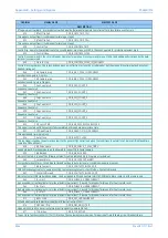
ORDINAL
SIGNAL NAME
ELEMENT NAME
DESCRIPTION
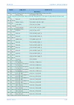
878
TOR Active
DDB_TOR_ACTIVE
Trip on re-close protection is active - indicated TOC delay timer has elapsed after circuit breaker opening, and remains in-service on auto-
reclosure for the duration of the trip on close window
879
SOTF Active
DDB_SOTF_ACTIVE
Switch on to fault protection is active - in service on manual breaker closure, and then remains in-service for the duration of the trip on close
window
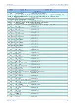
880
SysChks Inactive
DDB_SYSCHECKS_INACTIVE
System checks inactive (output from the check synchronism, and other voltage checks)
881
CS1 Enabled
DDB_CHECKSYNC_1_ENABLED
DDB input must be high to enable check sync stage 1 logic to operate. Defaults to high if not mapped in PSL; if mapped in PSL must be driven
high.
882
CS2 Enabled
DDB_CHECKSYNC_2_ENABLED
DDB input must be high to enable check sync stage 2 logic to operate. Defaults to high if not mapped in PSL; if mapped in PSL must be driven
high.
883
Check Sync 1 OK
DDB_CHECKSYNC_1_OK
Output from Check Sync logic, when enabled: indicates set conditions for sync check stage 1 are satisfied.
884
Check Sync 2 OK
DDB_CHECKSYNC_2_OK
Output from Check Sync logic, when enabled: indicates set conditions for sync check stage 2 are satisfied.
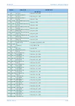
886
Live Bus
DDB_SYSCHECKS_BUS_LIVE
Indicates Bus input is live, i.e. voltage >= setting "Live Bus"
887
Dead Bus
DDB_SYSCHECKS_BUS_DEAD
Indicates Bus input is dead, i.e. voltage < setting "Dead Bus"
888
Live Line
DDB_SYSCHECKS_LINE_LIVE
Indicates Line input is live, i.e. voltage >= setting "Live Line"
889
Dead Line
DDB_SYSCHECKS_LINE_DEAD
Indicates Line input is dead, i.e. voltage < setting "Dead Line"
890
All Poles Dead
DDB_ALL_POLEDEAD
Pole dead logic detects 3 phase breaker open
891
Any Pole Dead
DDB_ANY_POLEDEAD
Pole dead logic detects at least one breaker pole open
892
Pole Dead A
DDB_PHASE_A_POLEDEAD
Phase A Pole Dead
893
Pole Dead B
DDB_PHASE_B_POLEDEAD
Phase B Pole Dead
894
Pole Dead C
DDB_PHASE_C_POLEDEAD
Phase C Pole Dead
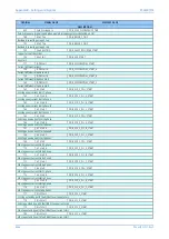
895
VTS Acc Ind
DDB_VTS_ACCELERATE_INPUT
Any Trip
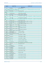
898
Ctl Check Sync
DDB_SYNC_CTRL_SYS_CHECK_OK
Input to the circuit breaker control logic to indicate manual check synchronization conditions are satisfied
900
Ext CS OK
DDB_CB1_EXT_CS_OK
External check-sync is OK
903
CB Open 3 ph
DDB_CB_OPEN
Circuit breaker is open, all three phases
904
CB Open A ph
DDB_CB_PHASE_A_OPEN
Circuit breaker A phase is open
905
CB Open B ph
DDB_CB_PHASE_B_OPEN
Circuit breaker B phase is open
906
CB Open C ph
DDB_CB_PHASE_C_OPEN
Circuit breaker C phase is open
907
CB Closed 3 ph
DDB_CB_CLOSED
Circuit breaker is closed, all three phases
908
CB Closed A ph
DDB_CB_PHASE_A_CLOSED
Circuit breaker A phase is closed
909
CB Closed B ph
DDB_CB_PHASE_B_CLOSED
Circuit breaker B phase is closed
910
CB Closed C ph
DDB_CB_PHASE_C_CLOSED
Circuit breaker C phase is closed
Summary of Contents for P4A
Page 2: ......
Page 20: ...Contents P54A B C E xviii P54xMED TM EN 1 ...
Page 27: ...CHAPTER 1 INTRODUCTION ...
Page 28: ...Chapter 1 Introduction P54A B C E 2 P54xMED TM EN 1 ...
Page 38: ...Chapter 1 Introduction P54A B C E 12 P54xMED TM EN 1 ...
Page 39: ...CHAPTER 2 SAFETY INFORMATION ...
Page 40: ...Chapter 2 Safety Information P54A B C E 14 P54xMED TM EN 1 ...
Page 52: ...Chapter 2 Safety Information P54A B C E 26 P54xMED TM EN 1 ...
Page 53: ...CHAPTER 3 HARDWARE DESIGN ...
Page 54: ...Chapter 3 Hardware Design P54A B C E 28 P54xMED TM EN 1 ...
Page 86: ...Chapter 3 Hardware Design P54A B C E 60 P54xMED TM EN 1 ...
Page 87: ...CHAPTER 4 SOFTWARE DESIGN ...
Page 88: ...Chapter 4 Software Design P54A B C E 62 P54xMED TM EN 1 ...
Page 99: ...CHAPTER 5 CONFIGURATION ...
Page 100: ...Chapter 5 Configuration P54A B C E 74 P54xMED TM EN 1 ...
Page 120: ...Chapter 5 Configuration P54A B C E 94 P54xMED TM EN 1 ...
Page 121: ...CHAPTER 6 CURRENT DIFFERENTIAL PROTECTION ...
Page 122: ...Chapter 6 Current Differential Protection P54A B C E 96 P54xMED TM EN 1 ...
Page 149: ...CHAPTER 7 AUTORECLOSE ...
Page 150: ...Chapter 7 Autoreclose P54A B C E 124 P54xMED TM EN 1 ...
Page 207: ...CHAPTER 8 CB FAIL PROTECTION ...
Page 208: ...Chapter 8 CB Fail Protection P54A B C E 182 P54xMED TM EN 1 ...
Page 219: ...CHAPTER 9 CURRENT PROTECTION FUNCTIONS ...
Page 220: ...Chapter 9 Current Protection Functions P54A B C E 194 P54xMED TM EN 1 ...
Page 244: ...Chapter 9 Current Protection Functions P54A B C E 218 P54xMED TM EN 1 ...
Page 247: ...CHAPTER 10 VOLTAGE PROTECTION FUNCTIONS ...
Page 248: ...Chapter 10 Voltage Protection Functions P54A B C E 222 P54xMED TM EN 1 ...
Page 261: ...CHAPTER 11 FREQUENCY PROTECTION FUNCTIONS ...
Page 262: ...Chapter 11 Frequency Protection Functions P54A B C E 236 P54xMED TM EN 1 ...
Page 268: ...Chapter 11 Frequency Protection Functions P54A B C E 242 P54xMED TM EN 1 ...
Page 269: ...CHAPTER 12 MONITORING AND CONTROL ...
Page 270: ...Chapter 12 Monitoring and Control P54A B C E 244 P54xMED TM EN 1 ...
Page 300: ...Chapter 12 Monitoring and Control P54A B C E 274 P54xMED TM EN 1 ...
Page 301: ...CHAPTER 13 SUPERVISION ...
Page 302: ...Chapter 13 Supervision P54A B C E 276 P54xMED TM EN 1 ...
Page 312: ...Chapter 13 Supervision P54A B C E 286 P54xMED TM EN 1 ...
Page 323: ...CHAPTER 14 DIGITAL I O AND PSL CONFIGURATION ...
Page 324: ...Chapter 14 Digital I O and PSL Configuration P54A B C E 298 P54xMED TM EN 1 ...
Page 336: ...Chapter 14 Digital I O and PSL Configuration P54A B C E 310 P54xMED TM EN 1 ...
Page 337: ...CHAPTER 15 FIBRE TELEPROTECTION ...
Page 338: ...Chapter 15 Fibre Teleprotection P54A B C E 312 P54xMED TM EN 1 ...
Page 354: ...Chapter 15 Fibre Teleprotection P54A B C E 328 P54xMED TM EN 1 ...
Page 355: ...CHAPTER 16 ELECTRICAL TELEPROTECTION ...
Page 356: ...Chapter 16 Electrical Teleprotection P54A B C E 330 P54xMED TM EN 1 ...
Page 366: ...Chapter 16 Electrical Teleprotection P54A B C E 340 P54xMED TM EN 1 ...
Page 367: ...CHAPTER 17 COMMUNICATIONS ...
Page 368: ...Chapter 17 Communications P54A B C E 342 P54xMED TM EN 1 ...
Page 439: ...CHAPTER 18 CYBER SECURITY ...
Page 440: ...Chapter 18 Cyber Security P54A B C E 414 P54xMED TM EN 1 ...
Page 457: ...CHAPTER 19 INSTALLATION ...
Page 458: ...Chapter 19 Installation P54A B C E 432 P54xMED TM EN 1 ...
Page 471: ...CHAPTER 20 COMMISSIONING INSTRUCTIONS ...
Page 472: ...Chapter 20 Commissioning Instructions P54A B C E 446 P54xMED TM EN 1 ...
Page 513: ...CHAPTER 21 MAINTENANCE AND TROUBLESHOOTING ...
Page 514: ...Chapter 21 Maintenance and Troubleshooting P54A B C E 488 P54xMED TM EN 1 ...
Page 530: ...Chapter 21 Maintenance and Troubleshooting P54A B C E 504 P54xMED TM EN 1 ...
Page 531: ...CHAPTER 22 TECHNICAL SPECIFICATIONS ...
Page 532: ...Chapter 22 Technical Specifications P54A B C E 506 P54xMED TM EN 1 ...
Page 558: ...Chapter 22 Technical Specifications P54A B C E 532 P54xMED TM EN 1 ...
Page 559: ...APPENDIX A ORDERING OPTIONS ...
Page 560: ...Appendix A Ordering Options P54A B C E P54xMED TM EN 1 ...
Page 565: ...APPENDIX B SETTINGS AND SIGNALS ...
Page 566: ...Appendix B Settings and Signals P54A B C E P54xMED TM EN 1 ...
Page 790: ...Appendix B Settings and Signals P54A B C E B224 P54xMED TM EN 1 ...
Page 835: ...APPENDIX C WIRING DIAGRAMS ...
Page 836: ...Appendix C Wiring Diagrams P54A B C E P54xMED TM EN 1 ...
Page 849: ......


