7 Protection Parameter Settings
P50 Agile P253
7-22
P253/EN M/C
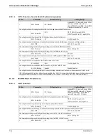
2.12.10
LIMIT NB STARTS
Sr. No
Parameter
Defaults setting
Setting/Ranges
1.
Hot Start Status
Disabled
Disabled/Enabled
This setting enables/disables hot start status function
2.
Hot Start NB
2
1 to 5 step of 1
This setting determines the number of hot starts allowed.
3.
Cold Strt Stat
Disabled
Disabled/Enabled
This setting enables/disables cold start status function
4.
Cold Start NB
3
1 to 5 step of 1
This setting determines the starting time delay.
5.
Supervising Time
10 Mins
1 to 120 min step 1 min
This setting enables/disables the supervision period for the number of hot and cold starts.
6.
T.Betw.St Status
Disabled
Disabled / Enabled
This enables/ disables the setting for time between two starts.
7.
Time Betwe Start
20 Mins
1 to 120min step 1min
This setting determines the minimum time between two starts.
8.
Inhib. Strt Time
10 Mins
1 to 120min step 1min
This setting determines the length of start inhibit signal once the maximum limit of either of the two counters (cold and hot) has been
reached
2.12.11
VIEW RECORDS
Sr. No
Parameter
Display value on LCD
1.
Fault Record
Display the Records of fault i.e. parameter value, flag of fault & date and time of Fault
2.
Event Record
Display of all digital events with time stamping (max 512 events)
3.
Maint Record
Display of error generated by relay if any, in case of failure of hardware
4.
Alarm Record
Display of alarm generated by relay & date and time of generated alarm.
Summary of Contents for P50 Agile P253
Page 3: ...P50 Agile P253 1 Introduction P253 EN M C 1 1 INTRODUCTION CHAPTER 1 ...
Page 4: ...1 Introduction P50 Agile P253 1 2 P253 EN M C ...
Page 11: ...SAFETY INFORMATION CHAPTER 2 ...
Page 12: ...Safety Information Pxxx 2 ...
Page 23: ...P50 Agile P253 3 Hardware Design P253 EN M C 3 1 HARDWARE DESIGN CHAPTER 3 ...
Page 24: ...3 Hardware Design P50 Agile P253253 3 2 P253 EN M C ...
Page 28: ...3 Hardware Design P50 Agile P253253 3 6 P253 EN M C E00276 Figure 2 Hardware design overview ...
Page 32: ...3 Hardware Design P50 Agile P253253 3 10 P253 EN M C ...
Page 33: ...P50 Agile P253 4 Front Panel P253 EN M C 4 1 FRONT PANEL CHAPTER 4 ...
Page 34: ...4 Front Panel P50 Agile P253 4 2 P253 EN M C ...
Page 39: ...P50 Agile P253 4 Front Panel P253 EN M C 4 7 Figure 2 USB port ...
Page 40: ...4 Front Panel P50 Agile P253 4 8 P253 EN M C ...
Page 41: ...P50 Agile P253 5 Configuration P253 EN M C 5 1 CONFIGURATION CHAPTER 5 ...
Page 42: ...5 Configuration P50 Agile P253 5 2 P253 EN M C ...
Page 154: ...5 Configuration P50 Agile P253 5 114 P253 EN M C ...
Page 155: ...P50 Agile P253 6 Protection Functions P253 EN M C 6 1 PROTECTION FUNCTIONS CHAPTER 6 ...
Page 156: ...6 Protection Functions P50 Agile P253 6 2 P253 EN M C ...
Page 182: ...7 Protection Parameter Settings P50 Agile P253 7 2 P253 EN M C ...
Page 203: ...P50 Agile P253 8 Monitoring Control P253 EN M C 8 1 MONITORING CONTROL CHAPTER 8 ...
Page 204: ...8 Monitoring Control P50 Agile P253 8 2 P253 EN M C ...
Page 222: ...8 Monitoring Control P50 Agile P253 8 20 P253 EN M C ...
Page 223: ...P50 Agile P253 9 SCADA Communications P253 EN M C 9 1 SCADA COMMUNICATIONS CHAPTER 9 ...
Page 224: ...9 SCADA Communications P50 Agile P253 9 2 P253 EN M C ...
Page 249: ...P50 Agile P253 10 Installation P253 EN M C 10 1 INSTALLATION CHAPTER 10 ...
Page 250: ...10 Installation P50 Agile P253 10 2 P253 EN M C ...
Page 260: ...11 Commissioning Instructions P50 Agile P253 11 2 P253 EN M C ...
Page 270: ...11 Commissioning Instructions P50 Agile P253 11 12 P253 EN M C ...
Page 272: ...12 Maintenance and Troubleshooting P50 Agile P253 12 2 P253 EN M C ...
Page 282: ...13 Technical Specifications P50 Agile P253 13 2 P253 EN M C ...
Page 292: ...13 Technical Specifications P50 Agile P253 13 12 P253 EN M C ...
Page 293: ...P50 Agile P253 14 Wiring Diagrams P253 EN M C 14 1 WIRING DIAGRAMS CHAPTER 14 ...
Page 294: ...14 Wiring Diagrams P50 Agile P253 14 2 P253 EN M C ...
Page 297: ......


