P50 Agile P253
8 Monitoring & Control
P253/EN M/C
8-13
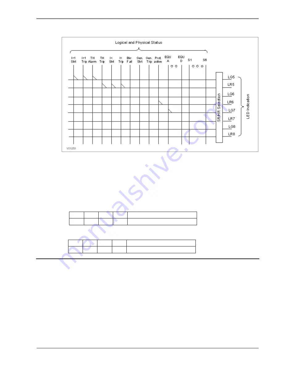
Figure 3: LEDs configuration logic
The functions that can be assigned to Green LED and Red LED are the same to relay contact.
All Green LEDs and Red LEDs can be individually set as self-reset or latching.
The selection of HR/SR type is made by changing bits value from 0 or 1 in
O/P Contact
Configuration
setting.
For Self-reset output contact, set bit 0
For Latch type (HR) output contact, set bit 1.
The bit position for Green LEDs is as shown in following table.
LG-8
LG-7
LG-6
LG-5
0
0
0
0
1 is HR type & 0 is SR type
The bit position for Red LEDs is as shown in following table.
LR-8
LR-7
LR-6
LR-5
0
0
0
0
1 is HR type & 0 is SR type
2.8
Logic Equations
The device supports 4 Logic AND equations which can be used to form Boolean functions using AND
operators. Any function available in the IO Mask can be assigned to any single equation. Maximum
numbers of signals that can be assigned to any equation depends on the number of functions
available in IO mask for assignment.
The Logic equations are identified as
AndLogic
A
, AndLogic
B
, AndLogic
C
and AndLogic
D
.
Any protection functions, Control Operation and opto I/Ps can be assigned to the AND logic equations
and result of equation can be time delayed and assigned to any output relays and LEDs. The relevant
settings are available under
O/P Relay
configuration menu.
The signals available for mapping to an equation are same as available for relay contacts and LEDs.
Summary of Contents for P50 Agile P253
Page 3: ...P50 Agile P253 1 Introduction P253 EN M C 1 1 INTRODUCTION CHAPTER 1 ...
Page 4: ...1 Introduction P50 Agile P253 1 2 P253 EN M C ...
Page 11: ...SAFETY INFORMATION CHAPTER 2 ...
Page 12: ...Safety Information Pxxx 2 ...
Page 23: ...P50 Agile P253 3 Hardware Design P253 EN M C 3 1 HARDWARE DESIGN CHAPTER 3 ...
Page 24: ...3 Hardware Design P50 Agile P253253 3 2 P253 EN M C ...
Page 28: ...3 Hardware Design P50 Agile P253253 3 6 P253 EN M C E00276 Figure 2 Hardware design overview ...
Page 32: ...3 Hardware Design P50 Agile P253253 3 10 P253 EN M C ...
Page 33: ...P50 Agile P253 4 Front Panel P253 EN M C 4 1 FRONT PANEL CHAPTER 4 ...
Page 34: ...4 Front Panel P50 Agile P253 4 2 P253 EN M C ...
Page 39: ...P50 Agile P253 4 Front Panel P253 EN M C 4 7 Figure 2 USB port ...
Page 40: ...4 Front Panel P50 Agile P253 4 8 P253 EN M C ...
Page 41: ...P50 Agile P253 5 Configuration P253 EN M C 5 1 CONFIGURATION CHAPTER 5 ...
Page 42: ...5 Configuration P50 Agile P253 5 2 P253 EN M C ...
Page 154: ...5 Configuration P50 Agile P253 5 114 P253 EN M C ...
Page 155: ...P50 Agile P253 6 Protection Functions P253 EN M C 6 1 PROTECTION FUNCTIONS CHAPTER 6 ...
Page 156: ...6 Protection Functions P50 Agile P253 6 2 P253 EN M C ...
Page 182: ...7 Protection Parameter Settings P50 Agile P253 7 2 P253 EN M C ...
Page 203: ...P50 Agile P253 8 Monitoring Control P253 EN M C 8 1 MONITORING CONTROL CHAPTER 8 ...
Page 204: ...8 Monitoring Control P50 Agile P253 8 2 P253 EN M C ...
Page 222: ...8 Monitoring Control P50 Agile P253 8 20 P253 EN M C ...
Page 223: ...P50 Agile P253 9 SCADA Communications P253 EN M C 9 1 SCADA COMMUNICATIONS CHAPTER 9 ...
Page 224: ...9 SCADA Communications P50 Agile P253 9 2 P253 EN M C ...
Page 249: ...P50 Agile P253 10 Installation P253 EN M C 10 1 INSTALLATION CHAPTER 10 ...
Page 250: ...10 Installation P50 Agile P253 10 2 P253 EN M C ...
Page 260: ...11 Commissioning Instructions P50 Agile P253 11 2 P253 EN M C ...
Page 270: ...11 Commissioning Instructions P50 Agile P253 11 12 P253 EN M C ...
Page 272: ...12 Maintenance and Troubleshooting P50 Agile P253 12 2 P253 EN M C ...
Page 282: ...13 Technical Specifications P50 Agile P253 13 2 P253 EN M C ...
Page 292: ...13 Technical Specifications P50 Agile P253 13 12 P253 EN M C ...
Page 293: ...P50 Agile P253 14 Wiring Diagrams P253 EN M C 14 1 WIRING DIAGRAMS CHAPTER 14 ...
Page 294: ...14 Wiring Diagrams P50 Agile P253 14 2 P253 EN M C ...
Page 297: ......


