5 Configuration
P50 Agile P253
5-34
P253/EN M/C
2.3.14
Disturbance Record Menu
2.3.14.1
View / Edit Settings
DISTURBANCE REC
Password protected window for “Disturbance Record” setting:
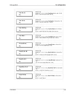
Trigger Position
Trigger Position
50%
Editable setting
By using the (+ /
5
) or (- /
6
) key, the desired Trigger Position can be
set. The setting range is from 10% to 90% in steps of 1.
2.3.15
Commissioning Test Menu
2.3.15.1
View / Edit Settings
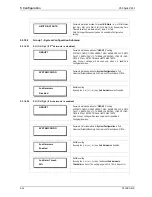
COMMISSION. TEST
Password protected window for “Commissioning Test” settings:
Test Mode, Test Pattern, Contact Test and Test LEDs.
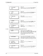
Test Mode
Disabled
Editable setting
By using the (+ /
5
) or (- /
6
) key, the desired Test Mode be set as
Disabled/Test Mode/Contacts Blocked.
Test Pattern
000000
Editable setting
By using the (+ /
5
) or (- /
6
) key, the desired Test Pattern can be set
as ‘1’=Operated / ‘0’=Not Operated.
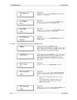
Contact Test
No Operation
Editable setting
By using the (+ /
5
) or (- /
6
) key, the desired Contact Test can be set
as No Operation / Apply Test / Remove Test
Test LEDs
No Operation
Editable setting
By using the (+ /
5
) or (- /
6
) key, the desired Test LEDs can be set as
No Operation / Apply Test.
2.3.16
Group 1 Menu
2.3.16.1
Edit Settings
GROUP 1
Password protected window for “GROUP 1’’ setting:
SYSTEM CONFIG, OVERCURRENT, NEG SEQUENCE O/C, EARTH
FAULT 1, EARTH FAULT 2, THERMAL OVERLOAD, LOSS OF LOAD,
CB FAIL, STALL DETECTION and LIMITS NB STARTS.
Note: Group 1 setting will be seen only when it is enabled in
Configuration setting.
Summary of Contents for P50 Agile P253
Page 3: ...P50 Agile P253 1 Introduction P253 EN M C 1 1 INTRODUCTION CHAPTER 1 ...
Page 4: ...1 Introduction P50 Agile P253 1 2 P253 EN M C ...
Page 11: ...SAFETY INFORMATION CHAPTER 2 ...
Page 12: ...Safety Information Pxxx 2 ...
Page 23: ...P50 Agile P253 3 Hardware Design P253 EN M C 3 1 HARDWARE DESIGN CHAPTER 3 ...
Page 24: ...3 Hardware Design P50 Agile P253253 3 2 P253 EN M C ...
Page 28: ...3 Hardware Design P50 Agile P253253 3 6 P253 EN M C E00276 Figure 2 Hardware design overview ...
Page 32: ...3 Hardware Design P50 Agile P253253 3 10 P253 EN M C ...
Page 33: ...P50 Agile P253 4 Front Panel P253 EN M C 4 1 FRONT PANEL CHAPTER 4 ...
Page 34: ...4 Front Panel P50 Agile P253 4 2 P253 EN M C ...
Page 39: ...P50 Agile P253 4 Front Panel P253 EN M C 4 7 Figure 2 USB port ...
Page 40: ...4 Front Panel P50 Agile P253 4 8 P253 EN M C ...
Page 41: ...P50 Agile P253 5 Configuration P253 EN M C 5 1 CONFIGURATION CHAPTER 5 ...
Page 42: ...5 Configuration P50 Agile P253 5 2 P253 EN M C ...
Page 154: ...5 Configuration P50 Agile P253 5 114 P253 EN M C ...
Page 155: ...P50 Agile P253 6 Protection Functions P253 EN M C 6 1 PROTECTION FUNCTIONS CHAPTER 6 ...
Page 156: ...6 Protection Functions P50 Agile P253 6 2 P253 EN M C ...
Page 182: ...7 Protection Parameter Settings P50 Agile P253 7 2 P253 EN M C ...
Page 203: ...P50 Agile P253 8 Monitoring Control P253 EN M C 8 1 MONITORING CONTROL CHAPTER 8 ...
Page 204: ...8 Monitoring Control P50 Agile P253 8 2 P253 EN M C ...
Page 222: ...8 Monitoring Control P50 Agile P253 8 20 P253 EN M C ...
Page 223: ...P50 Agile P253 9 SCADA Communications P253 EN M C 9 1 SCADA COMMUNICATIONS CHAPTER 9 ...
Page 224: ...9 SCADA Communications P50 Agile P253 9 2 P253 EN M C ...
Page 249: ...P50 Agile P253 10 Installation P253 EN M C 10 1 INSTALLATION CHAPTER 10 ...
Page 250: ...10 Installation P50 Agile P253 10 2 P253 EN M C ...
Page 260: ...11 Commissioning Instructions P50 Agile P253 11 2 P253 EN M C ...
Page 270: ...11 Commissioning Instructions P50 Agile P253 11 12 P253 EN M C ...
Page 272: ...12 Maintenance and Troubleshooting P50 Agile P253 12 2 P253 EN M C ...
Page 282: ...13 Technical Specifications P50 Agile P253 13 2 P253 EN M C ...
Page 292: ...13 Technical Specifications P50 Agile P253 13 12 P253 EN M C ...
Page 293: ...P50 Agile P253 14 Wiring Diagrams P253 EN M C 14 1 WIRING DIAGRAMS CHAPTER 14 ...
Page 294: ...14 Wiring Diagrams P50 Agile P253 14 2 P253 EN M C ...
Page 297: ......


