5 Configuration
P50 Agile P253
5-54
P253/EN M/C
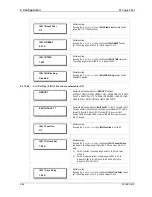
I<1 Status
Enabled
Editable setting
By using the (+ /
5
) or (- /
6
) key, I<1 Status is set as Enabled.
I<1 Current Set
1.00 A
Editable setting
By using the (+ /
5
) or (- /
6
) key, the desired I<1 Current Setting can
be set. The setting range is from 0.1 to 1 In in steps of 0.01 In
I<1 Time Delay
1.00 S
Editable setting
By using the (+ /
5
) or (- /
6
) key, the desired I<1
Time Delay can be
set. The setting range is from 0.2s to 100s in steps of 0.01s.
T inhib
12.00 S
Editable Setting
By using the (+ /
5
) or (- /
6
) key, the desired T inhib can be set. The
setting range is 0.05s to 300s in steps of 0.1s
2.3.16.9
Group 1 –CB Fail Submenu
2.3.16.9.1
Edit Settings
(if CB Fail Status is disabled)
GROUP 1
Password protected window for “GROUP 1’’ settings:
SYSTEM CONFIG, OVERCURRENT, NEG SEQUENCE O/C, EARTH
FAULT 1, EARTH FAULT 2, THERMAL OVERLOAD, LOSS OF LOAD,
CB FAIL, STALL DETECTION and LIMITS NB STARTS.
CB FAIL
Password protected window for CB FAIL settings i.e. CB Fail Status, CB
Fail Timer, CB Reset, I<, IN<, Remove I> Start and Remove IN> Start.
CB Fail Status
Disabled
Editable setting
By using the (+ /
5
) or (- /
6
) key, CB Fail Status is set as Disabled.
I<
1.00 A
By using the (+ /
5
) or (- /
6
) key, the desired I< can be set. The setting
range is from 0.05 to 32 In in steps of 0.01 In
IN<
1.00 A
By using the (+ /
5
) or (- /
6
) key, the desired IN< can be set. The
setting range is from 0.05 to 32 In in steps of 0.01 In
Summary of Contents for P50 Agile P253
Page 3: ...P50 Agile P253 1 Introduction P253 EN M C 1 1 INTRODUCTION CHAPTER 1 ...
Page 4: ...1 Introduction P50 Agile P253 1 2 P253 EN M C ...
Page 11: ...SAFETY INFORMATION CHAPTER 2 ...
Page 12: ...Safety Information Pxxx 2 ...
Page 23: ...P50 Agile P253 3 Hardware Design P253 EN M C 3 1 HARDWARE DESIGN CHAPTER 3 ...
Page 24: ...3 Hardware Design P50 Agile P253253 3 2 P253 EN M C ...
Page 28: ...3 Hardware Design P50 Agile P253253 3 6 P253 EN M C E00276 Figure 2 Hardware design overview ...
Page 32: ...3 Hardware Design P50 Agile P253253 3 10 P253 EN M C ...
Page 33: ...P50 Agile P253 4 Front Panel P253 EN M C 4 1 FRONT PANEL CHAPTER 4 ...
Page 34: ...4 Front Panel P50 Agile P253 4 2 P253 EN M C ...
Page 39: ...P50 Agile P253 4 Front Panel P253 EN M C 4 7 Figure 2 USB port ...
Page 40: ...4 Front Panel P50 Agile P253 4 8 P253 EN M C ...
Page 41: ...P50 Agile P253 5 Configuration P253 EN M C 5 1 CONFIGURATION CHAPTER 5 ...
Page 42: ...5 Configuration P50 Agile P253 5 2 P253 EN M C ...
Page 154: ...5 Configuration P50 Agile P253 5 114 P253 EN M C ...
Page 155: ...P50 Agile P253 6 Protection Functions P253 EN M C 6 1 PROTECTION FUNCTIONS CHAPTER 6 ...
Page 156: ...6 Protection Functions P50 Agile P253 6 2 P253 EN M C ...
Page 182: ...7 Protection Parameter Settings P50 Agile P253 7 2 P253 EN M C ...
Page 203: ...P50 Agile P253 8 Monitoring Control P253 EN M C 8 1 MONITORING CONTROL CHAPTER 8 ...
Page 204: ...8 Monitoring Control P50 Agile P253 8 2 P253 EN M C ...
Page 222: ...8 Monitoring Control P50 Agile P253 8 20 P253 EN M C ...
Page 223: ...P50 Agile P253 9 SCADA Communications P253 EN M C 9 1 SCADA COMMUNICATIONS CHAPTER 9 ...
Page 224: ...9 SCADA Communications P50 Agile P253 9 2 P253 EN M C ...
Page 249: ...P50 Agile P253 10 Installation P253 EN M C 10 1 INSTALLATION CHAPTER 10 ...
Page 250: ...10 Installation P50 Agile P253 10 2 P253 EN M C ...
Page 260: ...11 Commissioning Instructions P50 Agile P253 11 2 P253 EN M C ...
Page 270: ...11 Commissioning Instructions P50 Agile P253 11 12 P253 EN M C ...
Page 272: ...12 Maintenance and Troubleshooting P50 Agile P253 12 2 P253 EN M C ...
Page 282: ...13 Technical Specifications P50 Agile P253 13 2 P253 EN M C ...
Page 292: ...13 Technical Specifications P50 Agile P253 13 12 P253 EN M C ...
Page 293: ...P50 Agile P253 14 Wiring Diagrams P253 EN M C 14 1 WIRING DIAGRAMS CHAPTER 14 ...
Page 294: ...14 Wiring Diagrams P50 Agile P253 14 2 P253 EN M C ...
Page 297: ......


