Chapter 4. Ladder Diagram (LD) Programming
GFK-2950C
February 2018
75
4.2.6
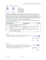
Logical AND, Logical OR, and Logical XOR
Each scan that power is received, the Logical function examines each bit in bit string IN1 and the
corresponding bit in bit string IN2, beginning with the least significant bit in each. You can specify a
string length of 1 to 256 WORDs or DWORDs. The IN1 and IN2 bit strings specified may overlap.
Logical AND
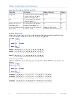
If both bits examined by the Logical AND function are 1, AND places a 1 in the corresponding location
in output string Q. If either bit is 0 or both bits are 0, AND places a 0 in string Q in that location.
AND passes power flow to the right whenever it receives power.
Tip:
You can use the Logical AND function to build masks or screens, where only certain bits are
passed (the bits opposite a 1 in the mask), and all other bits are set to 0.
Logical OR
If either bit examined by the Logical OR function is 1, OR places a 1 in the corresponding location in
output string Q. If both bits are 0, Logical OR places a 0 in string Q in that location. The function
passes power flow to the right whenever it receives power.
Tips:
■
You can use the Logical OR function to combine strings or to control many outputs with one
simple logical structure. The Logical OR function is the equivalent of two relay contacts in parallel
multiplied by the number of bits in the string.
■
You can use the Logical OR function to drive indicator lamps directly from input states or to
superimpose blinking conditions on status lights.
Logical XOR
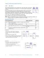
When the Exclusive OR (XOR) function receives power flow, it compares each bit in bit string IN1
with the corresponding bit in string IN2. If the bits are different, a 1 is placed in the corresponding
position in the output bit string.
For each pair of bits examined, if only one bit is 1, then XOR places a 1 in the corresponding location
in bit string Q. XOR passes power flow to the right whenever it receives power.
Tips for Logical XOR
■
If string IN2 and output string Q begin at the same reference, a 1 placed in string IN1 will cause
the corresponding bit in string IN2 to alternate between 0 and 1, changing state with each scan
as long as power is received.
■
You can program longer cycles by pulsing the power flow to the function at twice the desired
rate of flashing. The power flow pulse should be one scan long (one-shot type coil or self-
resetting timer).
■
You can use XOR to quickly compare two bit strings, or to blink a group of bits at the rate of one
ON state per two scans.
■
XOR is useful for transparency masks.
Summary of Contents for PACSystems RSTi-EP
Page 357: ......
Page 466: ...Chapter 9 Diagnostics GFK 2950C February 2018 451 ...


