Chapter 4. Ladder Diagram (LD) Programming
226
PACSystems* RX7i, RX3i and RSTi-EP CPU Programmer's Reference Manual
GFK-2950C
On Delay Timer
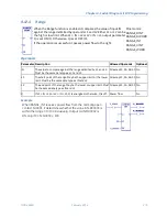
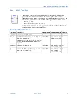
The On-Delay Timer (TMR) increments while it receives power flow and
resets to zero when power flow stops. The timer passes power after the
specified interval PV (Preset Value) has elapsed, as long as power is
received.
Mnemonics:
TMR_SEC
TMR_TENTHS
TMR_HUNDS
TMR_THOUS
The range for PV is 0 to +32,767 time units. If PV is out of range, it has no effect on the timer's word 2.
The state of this timer is retentive on power failure; no automatic initialization occurs at power-up.
Time may be counted in the following increments:
▪
Seconds
▪
Tenths (0.1) of a second
▪
Hundredths (0.01) of a second
▪
Thousandths (0.001) of a second
When TMR is invoked with its power flow input turned OFF, its Current Value (CV) is reset to zero,
and the timer does not pass power flow to the right. Each time the TMR is invoked with its power
flow input turned ON, CV is updated to reflect the elapsed time since the timer was reset. When CV
reaches PV, the timer function passes power flow to the right.
Notes:
▪
The best way to use a TMR function is to invoke it with a particular reference address exactly one
time each scan. Do not invoke a TMR with the same reference address more than once per scan
(inappropriate accumulation of time would result). When a TMR appears in a program block, it
will only accumulate time once per scan. Subsequent calls to that same program block within the
same scan will have no effect on its TMRs. Do not program a TMR function with the same
reference address in two different blocks. You should not program a JUMP around a timer
function. Also, if you use recursion (that is, having a block call itself either directly or indirectly),
program the program block so that it invokes the timer before it makes any recursive calls to
itself.
▪
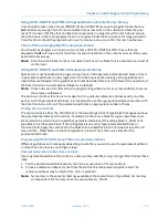
For information on using timers inside parameterized blocks, refer to
▪
A TMR timer expires (passes power flow to the right) the first scan that it is enabled if the
previous scan time was greater than PV.
▪
When TMR is used in a program block that is not called every scan, TMR accumulates time
between calls to the program block unless it is reset. This means that it functions like a timer
operating in a program with a much slower sweep than the timer in the main program block. For
program blocks that are inactive for a long time, TMR should be programmed to allow for this
catch-up feature. For example, if a timer in a program block is reset and the program block is not
called (is inactive) for 4 minutes, when the program block is called, four minutes of time will
already have accumulated. If the enable input is ON, these four minutes are applied to the timer
(i.e. CV is set to 4 minutes).
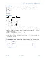
Timing Diagram
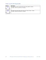
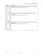
ENABLE goes high; timer begins accumulating time.
CV reaches PV; Q goes high and timer continues accumulating time.
Summary of Contents for PACSystems RSTi-EP
Page 357: ......
Page 466: ...Chapter 9 Diagnostics GFK 2950C February 2018 451 ...


