background image

Chapter 3

PROFIBUS Network Adapters 

20 

PACSystems* RSTi PROFIBUS and PROFINET Network Adapter

–August 2013 

GFK-2746B 


3.1


STXPBS001 

3.1.1


Interface 

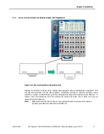
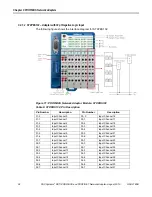
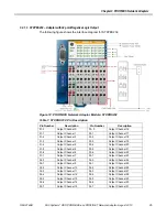
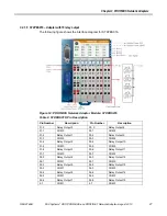
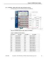
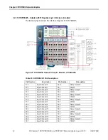
The following figure shows the interface diagram for STXPBS001. 


Figure 9: PROFIBUS Network Adaptor Module: STXPBS001 

 
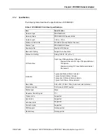
The following table lists the pin numbers and their description for STXPBS001. 
 

Table 2: STXPBS001: Pin Description 

Pin Number 

Description 

Pin Number 

Description 

System power 24v 

System power 0 v 

Ground 

Ground 

Field power 0v 

Field power 0v 

Field power 24v 

Field power 24v 


Summary of Contents for PACSystems RSTi

Page 1: ...GE Intelligent Platforms Programmable Control Products PACSystems RSTi PROFIBUS and PROFINET Network Adapter User s Manual GFK 2746B August 2013...

Page 2: ...e efforts have been made to be accurate the information contained herein does not purport to cover all details or variations in hardware or software nor to provide for every possible contingency in co...

Page 3: ...780 420 2010 if toll free 800 option is unavailable Technical Support Email support ip ge com Customer Care Email customercare ip ge com Primary language of support English Europe the Middle East and...

Page 4: ......

Page 5: ...Input 23 3 2 1 2 STXPBS132 Adapter with 32 pt Negative Logic Input 24 3 2 1 3 STXPBS232 Adapter with 32 point Negative Logic Output 25 3 2 1 4 STXPBS332 Adapter with 32 point Positive Logic Output 26...

Page 6: ...1 3 3 5 MSAC2 Abort PROFIBUS DP Extensions to EN 50170 62 3 3 6 MSAC2 Read PROFIBUS DP Extensions to EN 50170 62 3 3 7 MSAC2 Write PROFIBUS DP Extensions to EN 50170 63 3 3 8 Error Decode PROFIBUS DP...

Page 7: ...nd PROFINET Network Adapter August 2013 7 C Product Certifications and Installation Guidelines for Conformance 85 C 1 Important Notes 85 C 2 Safety Notes 85 C 3 Certifications 85 C 4 Government Regula...

Page 8: ......

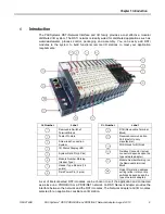
Page 9: ...lay LED System Data Pin 6 Pins Module Number Marking Header Type Header Type Module 16 points Field Power Pin 2 pins Sr Number Label RTB Removable Terminal Block Reserved communication Port Useful to...

Page 10: ...tion The Network Adapter must be connected to the left of the other RSTi modules in the I O station Within the RSTi station the bus connection power supply and power distribution are completed by conn...

Page 11: ...another This means that pretests can be carried out when the system is set up and that the whole system can be adapted and expanded 1 6 List of RSTi Network adapters RSTi PROFIBUS Network Adapters ST...

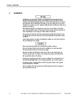
Page 12: ...rsonnel who install operate and maintain automation systems that contain these products must be trained and qualified to perform those functions Overloading power modules or Network adapter can result...

Page 13: ...2013 13 2 1 Module Mounting 2 1 1 How to Mount on DIN Rail 1 Press down the module lightly on the DIN Rail until it clicks locks Figure 1 Pressing down the module lightly 2 You can use the PUSH lock f...

Page 14: ...Adapter August 2013 GFK 2746B 2 1 2 How to dismount from DIN Rail 1 Pull down the locking mechanism by using small flat screw driver as in the following figures Figure 3 Pulling down the lock 2 Pull u...

Page 15: ...d with a small bladed screwdriver The clip will click and lock into the open position Install the module on the DIN rail firmly Once module is in place on the DIN rail push the clip upward to secure t...

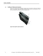
Page 16: ...and Removing Components To plug in the module use a small bladed screwdriver and push down the locking lever located at bottom of the module Install the module on DIN rail firmly push up the locking l...

Page 17: ...bus with 6 data pins and 2 field power pins Warning Do not touch data and field power pins in order to avoid damage by ESD noise 2 3 1 RSTi Bus Data Pin Field Power Pin Description Table 1 RSTi Bus Pi...

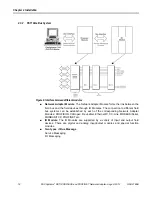
Page 18: ...d the field devices through IO Modules The connection to different field bus systems can be established by each of the corresponding Network Adapter Modules PROFIBUS CANopen DeviceNet Ethernet IP CC L...

Page 19: ...the status of Module network expansion units and field power It has got the PNO conformance certificate This means it has interoperability with other PROFIBUS products It supports the communication s...

Page 20: ...the interface diagram for STXPBS001 Figure 9 PROFIBUS Network Adaptor Module STXPBS001 The following table lists the pin numbers and their description for STXPBS001 Table 2 STXPBS001 Pin Description...

Page 21: ...tting Support Auto baud rate Station No Setting Rotary S W 1 2 x10 x1 I O Data Size Total Input 128bytes Output 128bytes Maximum Discrete I O Input 1024points Output 1024points Maximum Analog I O Inpu...

Page 22: ...eviceNet to internal logic Non isolation Internal logic to I O driver Isolation Field Power Supply voltage 24Vdc nominal Supply voltage range 11 28 8Vdc Field Power detection About 11Vdc Max Current F...

Page 23: ...nput Channel 1 03 1 Input Channel 17 01 2 Input Channel 2 03 2 Input Channel 18 01 3 Input Channel 3 03 3 Input Channel 19 01 4 Input Channel 4 03 4 Input Channel 20 01 5 Input Channel 5 03 5 Input Ch...

Page 24: ...03 1 Input Channel 17 01 2 Input Channel 2 03 2 Input Channel 18 01 3 Input Channel 3 03 3 Input Channel 19 01 4 Input Channel 4 03 4 Input Channel 20 01 5 Input Channel 5 03 5 Input Channel 21 01 6...

Page 25: ...t Channel 17 01 2 Output Channel 2 03 2 Output Channel 18 01 3 Output Channel 3 03 3 Output Channel 19 01 4 Output Channel 4 03 4 Output Channel 20 01 5 Output Channel 5 03 5 Output Channel 21 01 6 Ou...

Page 26: ...t Channel 17 01 2 Output Channel 2 03 2 Output Channel 18 01 3 Output Channel 3 03 3 Output Channel 19 01 4 Output Channel 4 03 4 Output Channel 20 01 5 Output Channel 5 03 5 Output Channel 21 01 6 Ou...

Page 27: ...ption Pin Number Description 01 0 Relay Output 0 03 0 Relay Output 8 01 1 COM 0 03 1 COM 2 01 2 Relay Output 1 03 2 Relay Output 9 01 3 COM 0 03 3 COM 2 01 4 Relay Output 2 03 4 Relay Output 10 01 5 C...

Page 28: ...iption Pin Number Description 01 0 Relay Output 0 03 0 Relay Output 8 01 1 COM 0 03 1 COM 8 01 2 Relay Output 1 03 2 Relay Output 9 01 3 COM 1 03 3 COM 9 01 4 Relay Output 2 03 4 Relay Output 10 01 5...

Page 29: ...nnel 1 03 1 Output Channel 1 01 2 Input Channel 2 03 2 Output Channel 2 01 3 Input Channel 3 03 3 Output Channel 3 01 4 Input Channel 4 03 4 Output Channel 4 01 5 Input Channel 5 03 5 Output Channel 5...

Page 30: ...el 1 03 1 Output Channel 1 01 2 Input Channel 2 03 2 Output Channel 2 01 3 Input Channel 3 03 3 Output Channel 3 01 4 Input Channel 4 03 4 Output Channel 4 01 5 Input Channel 5 03 5 Output Channel 5 0...

Page 31: ...put Channel 0 03 0 Relay Output 0 01 1 Input Channel 1 03 1 COM 0 01 2 Input Channel 2 03 2 Relay Output 1 01 3 Input Channel 3 03 3 COM 1 01 4 Input Channel 4 03 4 Relay Output 2 01 5 Input Channel 5...

Page 32: ...put Channel 0 03 0 Relay Output 0 01 1 Input Channel 1 03 1 COM 0 01 2 Input Channel 2 03 2 Relay Output 1 01 3 Input Channel 3 03 3 COM 0 01 4 Input Channel 4 03 4 Relay Output 2 01 5 Input Channel 5...

Page 33: ...0 Input Channel 0 03 0 Relay Output 0 01 1 Input Channel 1 03 1 COM 0 01 2 Input Channel 2 03 2 Relay Output 1 01 3 Input Channel 3 03 3 COM 1 01 4 Input Channel 4 03 4 Relay Output 2 01 5 Input Chan...

Page 34: ...0 Input Channel 0 03 0 Relay Output 0 01 1 Input Channel 1 03 1 COM 0 01 2 Input Channel 2 03 2 Relay Output 1 01 3 Input Channel 3 03 3 COM 1 01 4 Input Channel 4 03 4 Relay Output 2 01 5 Input Chan...

Page 35: ...rate Station No Setting Dip Switch 0 99 I O Data Size Total Input 36 bytes Output 36bytes Input 4 bytes Output 4 bytes for Base Module Input 32 bytes Output 32 bytes for IO Module Max Discrete I O In...

Page 36: ...olation System Power to internal logic Non isolation Internal logic to I O driver Isolation Field Power Supply voltage 24Vdc nominal Supply voltage range 11 28 8Vdc Max Current Field Power Contact Max...

Page 37: ...About 5 4K Output Specification Number of Output 32 Points 16 Points Type Negative Logic Positive Logic Negative Logic Output Load Current Maximum 0 5A 1pt 8A All Output Voltage 0Vdc 24Vdc 0Vdc Drop V...

Page 38: ...ng Red Minor Fault Recoverable Fault Solid Red Unrecoverable Fault An unrecoverable fault has occurred in self testing Rotary switch configuration error 3 2 3 2 Network Status LED NET Table 21 Network...

Page 39: ...s connected and run exchanging I O data Solid Red RSTi bus connection fault One or more IO module occurred in fault state Changed IO module configuration RSTi bus communication failure Flashing Red IO...

Page 40: ...or STXPBS001 3 2 4 2 STXPBS Dimension The following figure displays the dimension for STXPBS Figure 23 Dimension for STXPBS 3 2 4 3 Total IO The number of the module assembly that can be connected is...

Page 41: ...ND Data ground reference potential for VP 6 VP Supply voltage Plus P5V 7 8 RXD TXD N Receive Transmit data minus A wire 9 CNTR N Repeater Control Signal direction control All FieldBus devices which us...

Page 42: ...h built in series inductors Caution The use of an incorrect supply voltage or frequency can cause severe damage to the component 3 2 6 Choice of PROFIBUS data transfer cable type Depending on the appl...

Page 43: ...1000 400 200 100 100 100 Note In a PROFIBUS DP FMS installation you must choose a data transfer rate which is supported by all devices connected to the bus The chosen data transfer rate then determine...

Page 44: ...r connection 1 For safety supply system power and field power should be separated System Power for System PROFIBUS communications Field Power for I O field device connections 2 Make sure power supplie...

Page 45: ...is reserved to identify a broadcast exchange No response is returned to broadcast requests sent by the master Figure 26 MAC ID of a slave node The above figure shows MAC ID 27 2 10 7 1 of a slave nod...

Page 46: ...ure 27 DIP Switch Node Station Address Setting Example In order to change station ID to No 20 Bin 10100 Dip switch No 3 and 5 must be ON and others must be OFF Figure 28 Node Station Address Setting M...

Page 47: ...ed in the GSD directory The device names are placed into an internal list During the configuration the device specific data is retrieved directly from the GSD files If a DP Slave device does not appea...

Page 48: ...rk Adapter or STXPBS for all in one PROFIBUS Network Adapter Select OK A pop up menu will appear which can help you in configuring the I O station along with the I O modules 1 Assign a name descriptio...

Page 49: ...en STXPBS001 and modules will be stopped and each module will control its IO Data according to the Fault Action selected for it The Bus status will be ready IO status LED will blink To configure the I...

Page 50: ...ta Input values will be holding NET LED will be Green Network adaptor communication with master intact IO LED will be red and fault Loss of device logged in I O fault table 5 Restart on Bus Fault If B...

Page 51: ...action 00 INTEL 01 auto reset 01 00 00000001 00000000 00 PROFIBUS communication 00 Bus Stop IO fault action 01 MOTOROLA 00 Power reset 01 10 00000001 00010000 00 PROFIBUS communication 00 Bus Stop IO...

Page 52: ...ld Output 01 MOTOROLA 01 auto reset 00 02 00000000 00000010 10 Stay with last input 00 Bus Stop IO fault action 00 INTEL 00 Power reset 00 12 00000000 00010010 10 Stay with last input 00 Bus Stop IO f...

Page 53: ...Index 2 Read memory data from an IO module Slot 0 Index 254 Read vendor code from EEPROM directly Data Ln 1 Fixed Slot 0 Index 253 read FW revision Data Ln 4 Fixed for STXPBS001 1 all in one modules S...

Page 54: ...ng resister combination as follows Figure 32 Terminating Resistor Combination 3 2 9 I O Process Image Map An IO module may have three types of data I O data configuration parameter and memory register...

Page 55: ...5 The following figure shows the data flow of process image between network adapter and IO modules for STXPBS Figure 34 STXPBS Data flow between Network Adapter and IO Modules 3 2 9 1 Example of Input...

Page 56: ...rocess Image Mode Byte Slot Bit 7 Bit 6 Bit 5 Bit 4 Bit 3 Bit 2 Bit 1 Bit 0 Byte 0 0 AT2 1st input byte Base IO Byte 1 2nd input byte Base IO Byte 2 3rd input byte Base IO Byte 3 4th input byte Base I...

Page 57: ...Output Process Image Map Figure 36 Slot Configuration The following table lists the slot number and module description Table 30 Slot number and Module Description Slot Address Module Description 0 STX...

Page 58: ...st output byte Base IO Byte 1 2nd output byte Base IO Byte 2 3rd output byte Base IO Byte 3 4th output byte Base IO Byte 4 1 Empty Don t care Discrete Output 2 points Slot 1 Byte 5 2 Empty Don t care...

Page 59: ...EN 50170 MSAC1 Read Request Parameter Description Remote Address Slave Address 0 99 Slot Number Slot Number 0 32 0 STXPBS001 Index 1 Parameter 2 Memory 252 IO Module Vendor code Not used by user 253 R...

Page 60: ...1 Parameter 2 Memory Length 1 128 Data 1 Parameter 2 Memory Data 0 Offset Low Data 1 Offset High Data 2 User Data 3 Revision Not used by user Data 0 0xAE Data 1 0xBE Data 2 0xCE Data 3 0xDE Data 4 4 V...

Page 61: ...file_Features_Supported_2 PROFIBUS DP Extensions to EN50170 Profile_Ident_Number PROFIBUS DP Extensions to EN50170 Add_Addr_Param PROFIBUS DP Extensions to EN50170 S Addr 0 D Addr 0 MSAC2 Initiate Con...

Page 62: ...N50170 MSAC2_Read MSAC2_Write 3 3 6 MSAC2 Read PROFIBUS DP Extensions to EN 50170 MSAC2 Read Request Parameter Description C_Ref Communication Reference Slot Number Slot Number 0 32 0 STXPBS001 1 32 I...

Page 63: ...BS001 Index 1 Parameter 2 Memory Length 1 128 Data 1 Parameter 2 Memory Data 0 Offset Low Data 1 Offset High Data 2 User Data 3 Revision Data 0 0xAE Data 1 0xBE Data 2 0xCE Data 3 0xDE Data 4 4 Vendor...

Page 64: ...3 7 Reserved 8 Version conflict 9 Feature not supported 10 15 User specific Error Class 0xB Access class Error code 0 Invalid index 1 Write length error 2 Invalid slot 3 Type conflict 4 Invalid area 5...

Page 65: ...0 Diagnostic allocation Slot24 31 11 Diagnostic allocation Slot32 39 12 Reserved 13 14 15 Device Status Diagnostic Header Extended Diagnostic Device Status 16 Status Type 0xA0 Manufacture specific 17...

Page 66: ...Input update timeout 0x48 RSTi bus token fault 0xC1 Resource error of slot 0xC2 Not supported service from slot 0xC3 Attribute error from slot 0xC4 Slot is already in this mode 0xC5 Object conflict fr...

Page 67: ...figure shows the interface design for STXPNS001 Figure 37 PROFINET Network Adaptor Module STXPNS001 The following table lists the pin numbers and their description for STXPNS001 Table 32 STXPNS001 Pin...

Page 68: ...en red NET Status Indicator 1 green red IO Status Indicator 1 green Port1 Link Active Status Indicator 1 green Port2 Link Active Status Indicator 1 green Field Power Status indicator Communication Rat...

Page 69: ...0 1S OS Handle Unexpected Exceptions Solid Green Normal Operation The unit is operating in normal condition 4 1 3 2 Network Status LED NET Table 35 STXPNS001 Network Status LED Color Status Function...

Page 70: ...ule configuration RSTi Bus communication failure Word data type error Parameter setting error Flashing Red IO Configuration Failed Failed to initialize IO module Detected invalid IO module ID Overflow...

Page 71: ...llowing figure displays the dimension for STXPNS001 Figure 38 Dimension for STXPNS001 4 1 4 1 Total IO The number of the module assembly that can be connected is 32 The maximum length is 426mm These m...

Page 72: ...ication Interface for STXPNS001 Figure 39 Shielded RJ 45 Socket The following table describes the Signal Name and Description Table 39 Signal name and Description RJ 45 Signal Name Description 10 TD T...

Page 73: ...power Field power connections 1 For safety supply system power and field power should be separated a System Power for System PROFINET communications b Field Power for I O field device connections 2 M...

Page 74: ...y 192 168 0 1 1 99 Name of the station will be STXPNS001 xx xx is the value of Rotary Switch IP address will be read from flash memory When the rotary switch is not set to non zero 1 99 If the decimal...

Page 75: ...s must not have the format n n n n where n 0 999 The device name must not start with numbers Names must not begin with the character sequence port xyz where x y z 0 9 If you want to change the IP addr...

Page 76: ...on between STXPNS001 and modules will be stopped and each module will control its IO Data according to the Fault Action selected for it Reaction on RSTi Bus error Clear input image The input values ar...

Page 77: ...unication To configure I O station add a GE IP PROFINET master module at the desired slot in the RX3i PME project Ensure that you have the latest GSDML file imported Right click on master module and c...

Page 78: ...ow will open as shown below Figure 43 Change Module List Now start adding the IO modules as per the physical setup after you add all the desired IO modules select OK To configure PROFINET network adap...

Page 79: ...e options are a Clear Output images to 0 The communication between STXPNS001 and slots will run All outputs of Slot will be cleared The output value should be set to 0 but Bus will run IO status LED w...

Page 80: ...Last Image Input values will be holding NET LED will be Green Network adaptor communication with master intact IO LED will be red and fault Loss addition of device logged in I O fault table Ensure th...

Page 81: ...re there are no duplicate node addresses Check configuration of master for port settings time out data size etc Power cycle the network adapter to ensure applicability of correct baud rate parity byte...

Page 82: ...41 00 0A Active Digital Output Modules ST 2114 4 Points TTL Inverting 5Vdc 20mA 81 00 0D Active ST 2124 4 Points TTL Non Inverting 5Vdc 20mA 81 00 0F Active ST 221F 16 Points Sink Negative Logic 24Vd...

Page 83: ...it 41 43 23 Active ST 3624 4 Channels Voltage 0 5Vdc 12bit 41 43 24 Active ST 3644 4 Channels Voltage 0 5Vdc 14bit 41 43 25 Active ST 3702 2 Channels RTD Status 41 41 28 Active ST 3704 4 Channels RTD...

Page 84: ...ctive ST 5232 RS485 Communication 2Channel C1 0B 0B 46 Active ST 5351 SSI Interface 1CH C1 01 09 9E Active ST 5422 2 CH PWM output 1 5A 24Vdc source C1 05 01 57 Active ST 5442 2 CH PWM output 0 5A 24V...

Page 85: ...n of this equipment The examples and diagrams in this manual are included solely for illustrative purposes Because of the many variables and requirements associated with any particular installation GE...

Page 86: ...ISPR 22 and based on this commonality testing to the each individual standard was deemed inappropriate The FCC requires the following note to be published according to FCC guidelines Note This equipme...

Page 87: ...ations Storage Temperature Storage 40 to 85 Relative Humidity 5 90 Non condensing Protection Class IP20 Mounting DIN Rail C 5 2 PROFINET STXPNS001 Table 44 Environmental specification for STXPNS001 It...

Page 88: ...88 PACSystems RSTi PROFIBUS and PROFINET Network Adapter August 2013 GFK 2746B...

Page 89: ...stem 18 IOGuidePro Tool for Configuration Monitoring 10 LED Indicators Field Power Status LED 39 IO Module Status LED 39 Module Status LED 38 Network Status LED 38 STXPNS001 69 List of RSTi Network ad...

Page 90: ...are available on our web site www ge ip com Additional Resources For more information please visit the GE Intelligent Platforms web site www ge ip com 2013 GE Intelligent Platforms Inc All Rights Rese...

Reviews: