Chapter 3
.
PROFIBUS Network Adapters
42
PACSystems* RSTi PROFIBUS and PROFINET Network Adapter
–August 2013
GFK-2746B
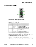
To prevent EMC interface from entering the device, the cable shield should be connected to
the functional ground of the device (generally the electrically conductive case). This is done
by connecting the cable shield to the metal case of the Sub-D connector and the functional
ground over a larger area. The bus connector must have a low-impedance connection to the
cable shield.
The data transfer technology of the serial bus system, which uses a shielded twisted pair
data cable, is described in the specification of the interface-immune RS 485 interface
standard. To allow correct bus termination, each station must connect the signals DGND and
VP (5V) to pins 5 and 6 of the connector respectively. The 5V supply for the terminating
resistors (VP) should have a minimum current rating of 10mA (the current load can increase
to 12mA if a NULL signal is sent through the bus). The current rating should be increased to
approximately 90mA if you need to supply other types of devices on the bus such as bus
terminals and optical fiber cable drivers. Due to the capacitive load of the station and the
resulting cable reflections, bus connectors should be provided with built-in series inductors.
Caution
The use of an incorrect supply voltage or frequency can cause severe damage to the
component.
3.2.6
Choice of PROFIBUS data transfer cable type
■
Depending on the application, the user can choose between electrical and optical fiber
data transfer cables. The following types of electrical data cables can be used:
Standard bus cable
Standard bus cable with halogen-free sheath (type FRNC)
Cable with PE Sheath for use in the food and manufacturing industries. (It differs
from the standard bus cable solely in the cable sheath).
Direct buried cable with additional protective sheath for lying in the ground.
Trailing cable: This is a special cable type which is used where parts of the machine
move occasionally or continuously.
Festooned cable: Compared to a trailing cable, a festooned cable has an additional
strain relief element.
■
The bus cable is specified in EN 50170 part 8-2 as "Cable Type A", and should comply
with the parameters in the following table. Cable Type B, which is also described in EN
50170, is outdated and should no longer be used.
■
Parameters for standard type A bus cables:
Table 25: Parameters for Standard Type A Bus Cables
Parameter
Cable Type A
Character
istic impedance in Ω
135..165 at a frequency of (3..20MHz)
Operating capacity(pF/m)
< 30
Loop resistance (Ω/km )
<=110
Core diameter (mm)
>0.64*
Cora cross-section (mm)
>0.34*
* The cable cross-sections used should be compatible with the mechanical specifications
of the bus interface connector.
Summary of Contents for PACSystems RSTi
Page 4: ......
Page 8: ......
Page 88: ...88 PACSystems RSTi PROFIBUS and PROFINET Network Adapter August 2013 GFK 2746B...


