GFK-2928
December 2017
7
Chapter 3
Application System Architecture
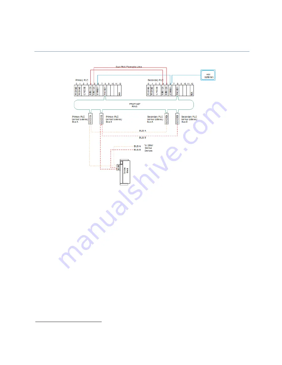
Figure 2: RX3i Genius Dual Bus Interfaced to RX3i via Genius Gateway Modules (GCG001)
A typical system consists of at least two RX3i racks, with the following components in each rack:
•
One or more power supplies
•
One PLC CPU module (IC695CPE330 or equivalent)
•
Two RMX reflective memory exchange modules (for CPU synchronization)
1
•
Fiber optic cables for the RMX modules
•
One or more PROFINET Controller modules
Additionally, the system will require the following items to interface with each dual Genius I/O network:
•
Four Genius Communications Gateway modules (two associated with the Primary PLC interface and
two with the Secondary PLC interface).
•
Cat5 or 6 Ethernet Cables to interconnect the Gateways with the PROFINET Controllers
•
Optional - interposing Ethernet switches that may be installed to provide additional MRP ring
functionality
•
Optional
–
Connectors that provide Hand Held Monitor attachment points for each of the Genius
busses. (GE catalog number 44A736310-001-R001. Refer to
Genius Hand-
Held Monitor User’s Guide
,
GFK-0121, page 2-9 for further information).
1
If a CPE400 is used, the RMX links are replaced with LAN3 links.


