Chapter 5. Function Block Diagram (FBD)
GFK-2950C
February 2018
241
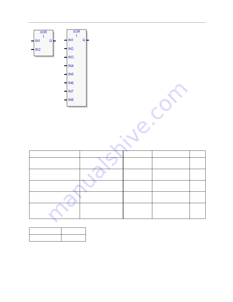
Minimum number
of inputs = 2
Maximum number
of inputs = 8
Logical XOR
If the bits in the strings examined by XOR are different, a 1 is
placed in the corresponding position in the output bit string.
For each pair of bits examined, if only one bit is 1, XOR
places a 1 in the corresponding location in string Q.
If both bits are 0, XOR places a 0 in the corresponding
location in string Q.
Tips:
▪
If string IN2 and output string Q begin at the same
reference, a 1 placed in string IN1 will cause the
corresponding bit in string IN2 to alternate between 0
and 1, changing state with each scan as long as input is
received.
▪
You can program longer cycles by pulsing the input to
the function at twice the desired rate of flashing. The
input pulse should be one scan long (one-shot type coil
or self-resetting timer).
▪
You can use XOR to quickly compare two bit strings, or
to blink a group of bits at the rate of one ON state per
two scans.
▪
XOR is useful for transparency masks.
Operands for AND, OR, and XOR
Parameter
Description
Allowed Types Allowed Operands
Optional
Solve Order
Calculated by the FBD
editor.
NA
NA
No
IN1
The value to operate on. BOOL, WORD
DWORD
All
No
IN2 (Must be the same data
type as IN1.)
The value to operate on. BOOL, WORD
DWORD
All
No
IN3 … IN8 (Must be the same
data type as IN1.)
Values to operate on.
BOOL, WORD
DWORD
All
Yes
Q (Must be the same data type
as IN1 and IN2.)
The operation’s result.
BOOL, WORD
DWORD
All except constants
and variables located
in %S memory
No
Properties for AND, OR, and XOR
Property
Valid Range
Number of Inputs 2 to 8
Summary of Contents for PACSystems RX7i
Page 357: ......
Page 466: ...Chapter 9 Diagnostics GFK 2950C February 2018 451...


