Chapter 5: Repair Procedures
Probe Panel Housing Repairs
5-16
Service Manual
5.5
Probe Panel Housing Repairs
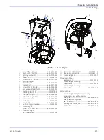
5.5.1 Probe Panel Housing Disassembly (
)
1.
For bedded model, remove the rear bedside panel by pushing the release button behind the bed, and
lifting up the bedside panel.
2.
For bedded model, tilt the bed so the back is down and the front is all the way up.
3.
Use a 3 mm hex key to remove the four socket head screws, four split ring washers, and four flat
washers that secure the bottom half of the probe panel housing.
4.
Remove the bottom half of the housing by sliding it forward.
5.5.2 SpO
2
Interface Board Replacement (
)
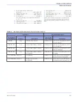
The logo on the probe panel housing indicates which SpO
2
system is installed:
For Masimo SET 1, see
. For Masimo SET 2 and Nellcor see
5.5.2.1 SpO
2
Interface Board Replacement for Masimo SET 1 (
1.
Remove the bottom end cap from the West Dovetail Rail and remove the decorative strip so that the
SpO
2
ground wire screw can be accessed.
2.
Remove the SpO
2
ground wire screw.
3.
Disassemble the probe panel housing following instructions 5.5.1.
4.
Remove the two button head screws securing the metal housing to the top of the Probe Panel housing
using a 2 mm hex key. Note location of ground strap for re-assembly.
5.
Unlatch and disconnect the SpO
2
cable leading to the east dovetail rail.
6.
Disconnect the SpO
2
Flex Circuit connector.
7.
Remove the metal housing/SpO
2
assembly and separate the two halves of the metal housing.
8.
To replace the board assembly use a 2 mm hex key to remove the 4 socket head screws and the lock
tooth washers that secure the SpO
2
interface board to the metal housing.
9.
Reverse the above procedure to reinstall SpO
2
board.
Masimo SET (1 or 2)
Nellcor
SpO
2
®
Summary of Contents for PANDA
Page 4: ...RH 2 Service Manual...
Page 12: ...ii Service Manual About this Manual User Responsibility...
Page 38: ...Chapter 1 Functional Description System Functions 1 14 Service Manual FIGURE 1 8 Power Failure...
Page 60: ...Chapter 2 Installation Maintenance and Checkout Scale Checkout Procedures 2 8 Service Manual...
Page 62: ...Chapter 3 Calibration Scale Calibration Bedded Models Only 3 2 Service Manual...
Page 172: ...Chapter 6 Illustrated Parts Wiring Diagrams 6 40 Service Manual...
Page 180: ...Appendix A Specifications SpO2 Specifications A 8 Service Manual...


