Chapter 5: Repair Procedures
Lower Unit Repairs (Bedded and Freestanding Models)
Service Manual
5-25
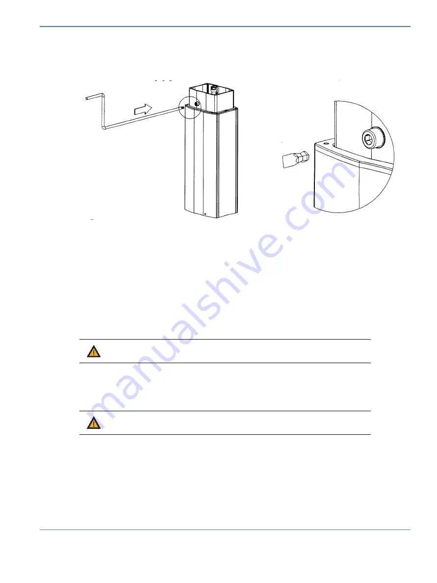
5.7.5.2 Adjusting Bed Height on Units with the Crank Handle
1.
Insert the crank handle into the socket, as shown below:
2.
Turn the crank handle to adjust the bed height:
•
Turn crank handle clockwise to raise the bed.
•
Turn crank handle counterclockwise to lower the bed.
5.7.6 Base and Rail Mounting Block Replacement (
) (Freestanding Models Only)
1.
Lay the Freestanding Warmer unit back on the ground.
2.
Use a socket wrench with a 15 mm deep socket to remove the two M10 nuts from the bottom of the
base and pull the base away from the rails to release the base.
3.
To remove the rail mounting block on each rail, use a 4 mm hex key to remove the M8 set screw and the
retaining plate and then use a 3 mm hex key to remove the four M4 screws attaching the mounting
block to the rail while holding the block and then pull it out of the rail. Discard the removed M4 screws.
Use new M4 screws for re-installation.
4.
Reverse steps for re-installation.
It is necessary to re-install the removed parts in the following order to avoid diminishing the joint
strength:
a.
Use a torque wrench to torque the four M4 screws on each mounting block to 21 +/- 3 lb-in
(2.37 +/- 0.34 N-m).
FIGURE 5-15. Crank Handle
Warning:
The base is 22 kg. Follow your local health and safety guidelines for
manual handling of heavy objects when lifting and carrying the heater head.
Warning:
Do not re-use the M4 screws once removed. Always use new M4 screws
for re-installation to avoid diminished joint strength.
Summary of Contents for PANDA
Page 4: ...RH 2 Service Manual...
Page 12: ...ii Service Manual About this Manual User Responsibility...
Page 38: ...Chapter 1 Functional Description System Functions 1 14 Service Manual FIGURE 1 8 Power Failure...
Page 60: ...Chapter 2 Installation Maintenance and Checkout Scale Checkout Procedures 2 8 Service Manual...
Page 62: ...Chapter 3 Calibration Scale Calibration Bedded Models Only 3 2 Service Manual...
Page 172: ...Chapter 6 Illustrated Parts Wiring Diagrams 6 40 Service Manual...
Page 180: ...Appendix A Specifications SpO2 Specifications A 8 Service Manual...


