Chapter 6: Illustrated Parts
Heater Housing
6-2
Service Manual
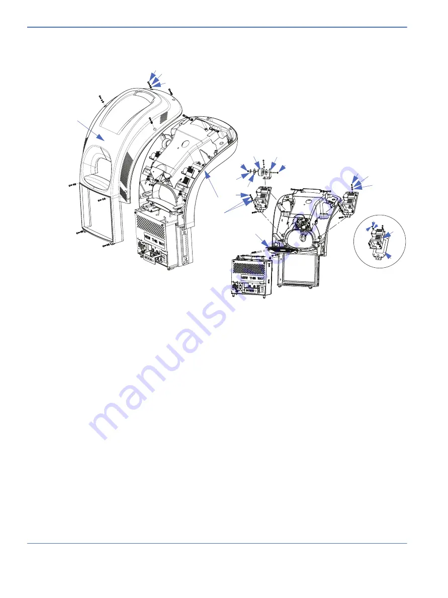
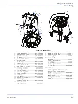
6.1 Heater Housing
1.
Heater head upper housing ..................6600-2034-500
2.
Heater head lower housing ............................. M1092513
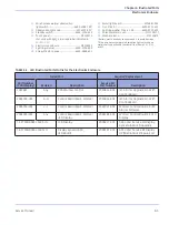
Requires Branding Label Set. Choose one:
Label Set Giraffe Branding ............................... M1111366
Label Set Panda Branding................................ M1111360
3.
Screw, M4 X 12, Skt Hd .............................6600-0707-410
4.
Split ring washer,
M4 X 4.1ID, 0.9 ..............................................6600-0713-403
5.
Washer, M4 X 4.3 ID, 0.8...........................6600-0712-403
6.
Washer, M3 X 3.2 ID, 0.5...........................6600-0712-402
7.
Screw, M3 x 8, Btn Hd................................6600-0706-405
8.
Power Supply 12V 65W................................ 2075961-001
9.
Power Supply brkt.......................................6600-2097-500
10.
Alarm light lens............................................ 6600-2043-500
11.
Spit ring washer, M3 ..................................6600-0713-402
12.
Harness Power Factor Correction..................M1113026
13.
Inductor mounting bracket...............................M1114499
14.
Lock nut........................................................... 6600-0714-402
15.
Washer, M4.................................................... 0402-1133-300
16.
Toroid mtg, washer,
0.175ID x 0.875OD.................................................M1114284
17.
Screw, M4 x 40 Btn. Hd...........................6600-0706-416*
18.
Nut, M4............................................................ 6600-0711-407
19.
Lockwasher, M4
Int. Tooth......................................................... 6600-0713-432
*Install heat shrink tubing on screw shaft.
FIGURE 6-1. Heater Housing
1
2
3
5
6
7
14
9
17
8
12
13
4
15
16
18
19
3
5
4
3
6
11
7
10
Summary of Contents for PANDA
Page 4: ...RH 2 Service Manual...
Page 12: ...ii Service Manual About this Manual User Responsibility...
Page 38: ...Chapter 1 Functional Description System Functions 1 14 Service Manual FIGURE 1 8 Power Failure...
Page 60: ...Chapter 2 Installation Maintenance and Checkout Scale Checkout Procedures 2 8 Service Manual...
Page 62: ...Chapter 3 Calibration Scale Calibration Bedded Models Only 3 2 Service Manual...
Page 172: ...Chapter 6 Illustrated Parts Wiring Diagrams 6 40 Service Manual...
Page 180: ...Appendix A Specifications SpO2 Specifications A 8 Service Manual...


