Chapter 6: Illustrated Parts
Base Assembly (Bedded Models Only)
6-10
Service Manual
6.4 Base Assembly (Bedded Models Only)
6.4.1 Elevating Column Special Instructions
Depending on the age of a unit, one of two elevating columns are used. Newer units display a label with a
part number near the top of the elevating column. Older units do not display a label. Refer to
for
on page 6-11 for part numbers that differ
between the two variants of the elevating column.
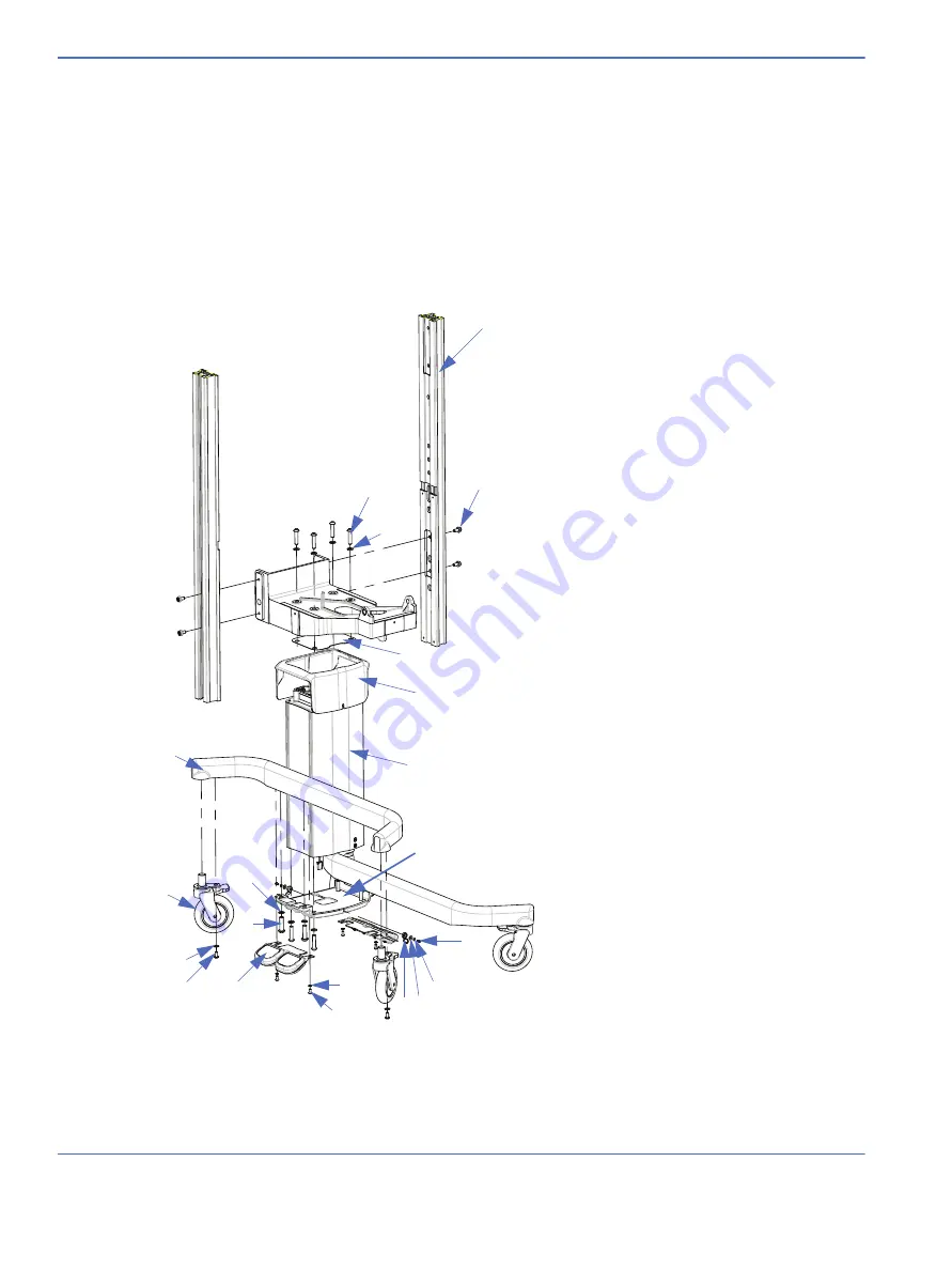
FIGURE 6-8. Base Assembly
1
1.
Dovetail rail (includes labels) .......................M1118409
2.
.
3.
.
4.
Screw, M8 x 20, skt flange lock........ 6600-1295-400
5.
Insulating sheet - Refer to
6.
.
7.
Elevating Column - Refer to
.
8.
.
9.
Hinged screw cover. 1/4..................... 6600-1206-403
10.
Screw, M4 X 10 Btn Hd ........................ 6600-0706-409
11.
Split ring washer, M4 X 4.1ID, 0.9.... 6600-0713-403
12.
Washer, M4 X 4.3 ID, 12 OD............... 6600-0712-446
13.
Lock washer, M6 X 6.4ID, 0.7,
Ext Tooth.................................................... 6600-0713-445
14.
Screw, M6 X 12 Btn Hd ........................ 6600-0706-427
15.
Foot switch ..........................................................M1108745
16.
Screw, M8x16, Btn Hd Nylock........... 6600-0706-435
17.
Washer, M8 X 8.4 ID, 1.6...................... 6600-0712-406
18.
Caster.......................................................... 6600-0890-400
19.
Split ring washer,
M12 X 12.2 ID, 2.5 .................................. 6600-0713-408
20.
Screw, M12 X 45, Btn Hd..................... 6600-0706-449
21.
Leg ................................................................ 6600-1599-500
22.
Plug M20 Thrd for fixed adjustable base
(not shown) ..........................................................M1079772
4
2
3
5
6
7
8
21
18
17
16
15
19
20
13
14
9 12
11
10
Summary of Contents for PANDA
Page 4: ...RH 2 Service Manual...
Page 12: ...ii Service Manual About this Manual User Responsibility...
Page 38: ...Chapter 1 Functional Description System Functions 1 14 Service Manual FIGURE 1 8 Power Failure...
Page 60: ...Chapter 2 Installation Maintenance and Checkout Scale Checkout Procedures 2 8 Service Manual...
Page 62: ...Chapter 3 Calibration Scale Calibration Bedded Models Only 3 2 Service Manual...
Page 172: ...Chapter 6 Illustrated Parts Wiring Diagrams 6 40 Service Manual...
Page 180: ...Appendix A Specifications SpO2 Specifications A 8 Service Manual...


