Chapter 1: Functional Description
System Functions
Service Manual
1-11
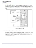
1.3.2 Hands Free Alarm Silence
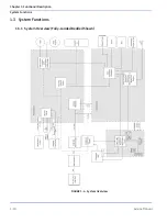
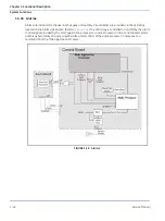
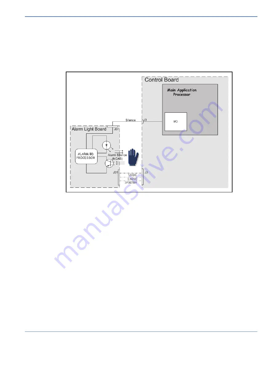
This processor-controlled circuitry resides on the Alarm Light Board. (Refer to
.) The user input is
accomplished with an infrared emitter/receiver pair. The emitter/receiver pair is monitored by the alarm
light microprocessor, which sends the alarm silence signal to the main application processor. The main
application processor uses this signal as one of two inputs to determine whether the alarm should be
silenced. The Hands Free Alarm Silence may be enabled/disabled/disengaged through Service Mode.
1.3.3 Watchdog
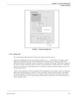
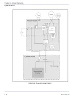
The system incorporates smart monitoring mechanisms that allow three of the processors to monitor each
other in order to detect abnormal operation. (Refer to
.) The audio processor functions as the
master watchdog processor and ensures the main application processor is responding normally. If the
audio processor detects abnormal functioning of the main processor it opens the heater safety relay and
activates a high priority alarm.
The main application processor ensures the heat control processor is responding normally. If the main
application processor detects abnormal functioning of the heat control processor it opens the heater safety
relay, activates the high priority alarm and displays a system fail message. A power cycle is required to
return the system to use.
An independent hardware circuit monitors the audio processor to ensure it is functioning normally. In the
event the audio processor does not respond normally the hardware circuit will reset the audio processor
causing a system fail condition. A power cycle is required to return the system to use.
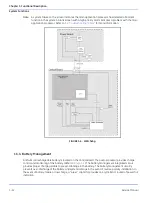
FIGURE 1-5. Hands Free Alarm Silence
Summary of Contents for PANDA
Page 4: ...RH 2 Service Manual...
Page 12: ...ii Service Manual About this Manual User Responsibility...
Page 38: ...Chapter 1 Functional Description System Functions 1 14 Service Manual FIGURE 1 8 Power Failure...
Page 60: ...Chapter 2 Installation Maintenance and Checkout Scale Checkout Procedures 2 8 Service Manual...
Page 62: ...Chapter 3 Calibration Scale Calibration Bedded Models Only 3 2 Service Manual...
Page 172: ...Chapter 6 Illustrated Parts Wiring Diagrams 6 40 Service Manual...
Page 180: ...Appendix A Specifications SpO2 Specifications A 8 Service Manual...


