– 55 –
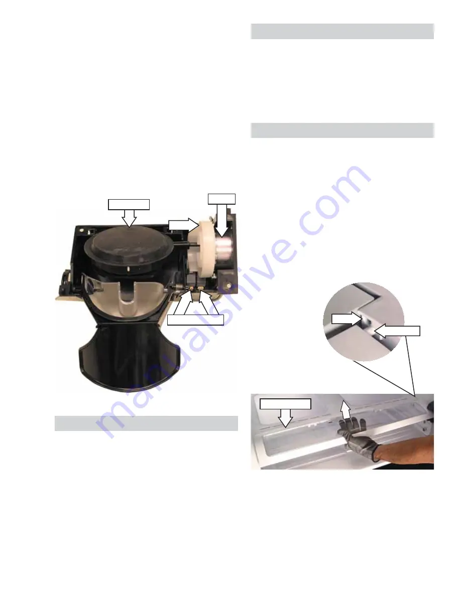
The duct door motor rotates an eccentrically shaped
plastic cam which operates the duct door. The cam
operates 2 route switches attached to the dispenser
assembly. The switches inform the main board the
position of the duct door so the auger and/or cube
solenoid can be activated. If communication is lost
between the switches and the board, because of a
switch failure for example, the symptom usually will
be continuous operation of the duct door.
The duct door motor operates at 120 VAC when
energized by the main control board.
The motor has resistance value of approximately
1.79K
Ω
. Check for the approximate resistance value
of the motor on the main board from CN70 pin 1 to
CN73 pin 9.
Cam
Duct Door
Motor
Route Switches
Dispenser Heater
The dispenser heater ensures that the dispensing
recess does not sweat in high humidity. The
dispenser heater operates at 120 VAC when
energized by the main control board.
The heater has resistance value of approximately
4.4K
Ω
. Check for the approximate resistance value
of the heater on the main board from CN70 pin 3 to
CN1 pin 3.
Note:
The dispenser heater is integral to the foamed
in place dispenser recess in the left-side refrigerator
door and is not replaceable.
Vegetable and Fruit Drawers Shelf
To remove the
vegetable and fruit drawers
shelf
:
Pull the 2 fruit and vegetable drawers out to the
1.
stop position. Lift and remove the drawers.
Lift and pull out the shelf.
2.
4. Lift and pull out the drawer cover.
5. Lift the front of the pantry shelf and pull it out of
the refrigerator.
Hinge Pin
Hole
Drawer Cover
Pantry Drawer Assembly
To remove the pantry drawer assembly:
Pull the 2 fruit and vegetable drawers out to the
1.
stop position. Lift and remove the drawers.
Pull the pantry drawer out to the stop position.
2.
Lift and remove the drawer.
Carefully lift the center of the drawer cover up
3.
while pushing the cover to the left. When the
right side hinge pin has disengaged from the
hole in the rail assembly, slide the right side of
the cover out.


