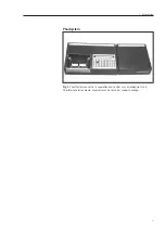
background image

Phast System

user

manual

automated electrophoresis

um

  80-1320-15  Edition  AI

Summary of Contents for PhastSystem

Page 1: ...Phast System user manual automated electrophoresis um 80 1320 15 Edition AI ...

Page 2: ......

Page 3: ...stem on 33 4 4 Before use 33 5 Operation 35 5 1 Programmingseparationprocedures 35 5 2 Sampleapplication 39 5 3 Running IEF media 41 5 4 Running electrophoresis media 46 5 5 Programmingdevelopmentprocedures 50 5 6 Running a development method 54 5 7 Cleaning method 57 5 8 Temperaturecompensation 59 6 Evaluation and presentation of data 65 6 1 Preservation 65 6 2 Evaluation 67 7 Maintenance and tro...

Page 4: ...ly tested to ensure that it meets its published specifications The warranty included in the conditions of delivery is valid only if the product has been installed and used according to the instructions supplied by GE Healthcare Bio Sciences AB GE Healthcare Bio Sciences AB shall in no event be liable for incidental or consequential damages including without limitation lost profits loss of income l...

Page 5: ...gel using PhastSystem with PhastGel separation media Flow diagram for PhastSystem Separation and control unit Development unit Place 1 or 2 gels on Place gel s in the separation bed 3 min development chamber 1 min Load PhastGel Select a programmed sample applicator s 3 min development method and press the start button Select a programmed when method stops 30 90 min separation method and press the ...

Page 6: ... Ordering information and technical data gives you all information needed to order the products mentioned in this manual You will also find a list of the most common spare parts required for maintenance of PhastSystem A list of the technical data on PhastSystem instruments and PhastGel media and accessories is also included Chapter 9 Separation technique files you will find optimized methods for a...

Page 7: ...7 Phastsystem Fig 1 PhastSystem consists of a separation and control unit a development unit PhastGel separation media accessories and a technical support package 1 Introduction ...

Page 8: ...8 ...

Page 9: ...ol unit and development unit according to your local electricity supply To do this Check the voltage range of the mains electricity supply Set the voltage selector to the appropriate setting according to the table below Voltage range Voltage selector setting For120 V model instruments 90 110 100 108 132 120 For 220 V model instruments 198 242 220 230 216 264 240 Important Always disconnect the mai...

Page 10: ... the instrument 1 Regularly check all insulation cables take care not to damage the units especially the separation compartments lid Note For full safety it is important that the lid is not tampered with 2 Ensure that the mains cables are plugged into fully grounded mains outlets 3 Allow only authorized service representatives to service or work on the electrical circuitry of PhastSystem 4 Avoid s...

Page 11: ...ocessor in the separation and control unit controls and regulates all parameters during separation and development runs Methods are programmed using the keyboard and stored in a semiconductor memory This memory is guarded by a battery so that methods are not lost when the system is turned off or if mains power fails Every time the system is turned on the microprocessor does a diagnostic test to ma...

Page 12: ... 13 If the lid is opened during a run the high voltage supply switches off automatically to eliminate electrical hazard An alarm will sound until the lid is closed or until the run is paused Fig 2 Separation compartment Sample application Samples are applied to gels with PhastGel sample applicators These small comb like pieces have a series of capillary wells Samples are drawn into the capillaries...

Page 13: ...m instruction and up to nine steps For each step the voltage current power separation bed temperature and duration of the step in volthours is programmed Before a separation method is started the sample applicator arm rests a few millimeters above the gels After a programmed interval during the run the applicator arm is lowered to apply the samples to the gels After a programmed interval the appli...

Page 14: ...Cooling capacity The cooling capacity of the separation bed will depend on the following 1 the ambient temperature 2 the power applied to the gels and 3 if one or two gels are run Fig 4 below illustrates the separation bed temperature versus time for native PAGE SDS PAGE and IEF runs The running conditions are given in the caption under the graph A slight temperature drift can be seen for the IEF ...

Page 15: ...ing foil a rotating gel holder for one or two gels a temperature and level sensor on the underside of the lid and ten ports through which the development chamber can be filled and emptied Ports labelled 1 9 are used to connect development solutions to the development chamber The port labelled 0 is reserved for waste that is solutions only exit through this port The gel holder liquid level sensor a...

Page 16: ...he gel the chamber can heat solutions up to 50 C is programmed As programming options each development method can have a temperature compensation curve and an extra alarm to sound at a set time during the run More information about temperature compensation is given in Development procedures section 5 3 Once the bottles of development solution are connected to the ports by the PVC tubing the gels a...

Page 17: ...stance of a polymer depends on many factors including the temperature and concentration of the solution the application a compound that swells may function well as a static seal yet fail in dynamic applications and the period of exposure Table 1 below is intended as a general guide for the chemical resistance of the wetted parts in the development unit If you are in doubt about the resistance of w...

Page 18: ...arbons and bleach centration in high concentration alcohols alde hydes and ketones 1 These parts are illustrated on pages 16 17 and 79 4 Ethylene propylene copolymer and terpolymer 2 Polyvinylidine fluoride 5 Polypropylene or polypropene 3 Polyvinyl chloride At present PhastGel media are available for four types of electrco phoretic techniques native polyacrylamide gel electrophoresis PAGE in grad...

Page 19: ...irst concentrated in a porous stacking gel zone they then move into the separation gel zone where they are separated according to size The migration distance of a protein is related to the logarithm of its molecular weight MW Molecular weights are easily estimated using one of the GE Healthcare molecular weight calibration kits See Evaluation and presentation of data chapter 6 for instructions Sev...

Page 20: ...gesfor PhastGel gradient media with respect to the molecular weight distribution of proteins in both denatured and non denatured form Fig 9 The approximate molecular weight separation ranges of PhastGel gradient media are superimposed on a histogram showing the molecular weight distribution of denatured proteins The histogram is made up to data collected from 530 proteins Each bar spans 10 000 dal...

Page 21: ...re used for each gel one at the cathode one at the anode The electrodes rest on the strips during electrophoresis and transfer current and voltage to the gel PhastGel buffer strips are individually sealed in airtight packages Once the buffer strips are removed from the package they must be used immediately PhastGel Blue R PhastGel Blue R is a Coomassie R 350 stain stamped into convenient tablet fo...

Page 22: ...ota tion marks Turning on the system The power on off button is placed at the back of the separation and control unit The microprocessor automatically runs a diagnostic test every time the unit is turned on The test includes the temperature sensors back up battery and level sensor When the system is turned on the display shows DIAGNOSTICS IN PROGRESS After a few seconds the display changes to DIAG...

Page 23: ...nditions during a run and help messages which include messages for power failures and programming and system errors Fig 11 Keyboard and display Numeric pad The numeric pad on the right of the keyboard is used to enter parameters when programming a method or starting a separation or development run 3 5 The keyboard 3 Description of the system ...

Page 24: ... be erased The decimal or period key is used when entering a number containing a decimal point for example 2 4 volts and when entering a method number and method step for example 1 2 step 2 of method 1 This key must be pressed even though the decimal point is shown on the display Fig 13 Programming keys 3 Description of the system ...

Page 25: ... these keys longer than one second These keys also serve as step ping keys for selecting characters when naming a method step forward press to move to the next step in a method step backward press to move to the previous step in a method You can move quickly through a method by depressing these keys longer than one second These keys also serve to select a method number when naming a method name me...

Page 26: ... display COPY SEP METHOD FROM 0 0 TO 0 0 dc or COPY DEV METHOD FROM 0 00 TO 0 00 do To copy a method enter the source method number at the cursor for example enter 1 COPY SET METHOD FROM 1 0 TO 0 0 do Press to move the cursor to the next field and then enter the destination method number for example enter 2 COPY SEP METHOD FROM 1 0 TO 2 0 Press do to confirm Method one will be copied over to metho...

Page 27: ... SEP 1 4 0000V 00 0mA 0 0W 00 C 0000Vh Step 4 is now ready for programming When you insert a step your are actually moving all the steps after the inserted one down to create a free step for programming In the example above step 4 becomes step 5 step 6 becomes step 7 and so on The help return key help return press to display help messages after an alarm sound after you press a programming key or a...

Page 28: ...rily Press again to continue the run from where it left off When you pause a run the corresponding LED will blink At 20 second intervals a short alarm will sound to remind you that a method is paused Once you press a pause key the display will show the step number and the number of volthours or minutes that elapsed during that step for example SEP 1 2 PAUSE 68 Vh or DEV 1 08 PAUSE t 10 0 min Durin...

Page 29: ...t 15 C Press do to turn the standby temperature on or off The monitoring keys SEP real condition Press to monitor the progress of a running separation method DEV real condition Press to monitor the progress of a running development method Press SEP real condition to monitor the progress of the entire method for example if method 1 is running the display may look like this SEP 1 3 1500V 02 0mA 3 0W...

Page 30: ...30 ...

Page 31: ...u should ever need to ship the unit Leaving the screw in place will make the unit noisier but will not affect the operation Unpacking the electrodes Carefully remove the plastic packing material from the electrode unit in the separation compartment of the separation and control unit Check that the electrodes are straight Voltage selector setting PhastSystem instruments are available in two version...

Page 32: ...ppropriate setting according to the table below Voltage range Voltage selector setting For 120 V model instruments 90 110 100 108 132 120 For 220 V model instruments 198 242 220 230 216 264 240 Fuses Each unit has two fuses Check that the fuses are correctly installed and intact Connecting the units Connect the separation and control unit to the development unit with the communication cable code n...

Page 33: ...the underside of the lid in the development chamber enclosed in stainless steel These are calibrated before shipment but you may want to check them before using PhastSystem The sensors can be checked and calibrated individually See the chapter on Maintenance for instructions Before using the development unit we recommend that you run a cleaning method to remove dust accumulated during storage and ...

Page 34: ...34 ...

Page 35: ...ication By pressing step forward twice the first step of method 1 appears on the display SEP 1 1 0000V 00 0mA 0 0W 00 C 0000Vh Each method step finishes after a programmed number of volthours A method step can have up to 9999 volthours You must also pro gram the following parameters for each step Voltage in volts V 1 to 2000 V Current in milliamperes mA 0 1 to 50 0 mA Power in watts W 0 1 to 7 0 W...

Page 36: ...wer for two gels exceeds the maximum values Thus the limiting values for each gel in this example are the maximum available How to program a method A step by step instruction for programming a separation method is given below Remember that help messages can be accessed at any cursor position by pressing help return Selecting a method 1 Press SEP method file The method numbers that are free for pro...

Page 37: ...1 0000 Vh 12 Press and enter the time volthours in the current step where the sample will be applied to gel step 1 in this example For example 75 volthours SAMPLE APPL DOWN AT 3 1 0075 Vh 13 Press step forward to program the second sample application instruction Enter the step number can be the same as for applicator down press and enter the volthours that will elapse before the sample applicator ...

Page 38: ...at is method 3 contains only one step After 9 steps in the method the display will show END OF METHOD In summary for the above example the sample applicators will be lowered onto the gels after 75 Vh during step 1 During this 75 Vh period the sample applicators can be loaded An alarm will sound after 73 Vh as a warning that sample application will occur in 2 Vh After 150 Vh in step 1 the sample ap...

Page 39: ...un see p 44 or 51 Editing a running method To edit a running method you must first press SEP pause continue unless you only want to program or change the extra alarm Then select the method in the SEP method file To change an entry in a running method follow the directions above for editing a programmed method You can delete or insert a step in a running method only if the deleted or inserted step ...

Page 40: ...tective cover facing upwards over the lane of holes 3 Run a pen or other hard object along the lane of wells to make depressions in the Parafilm 4 Remove the protective cover and place the Parafilm on a table so that the depressions can be filled with sample Fig 16 Preparing sample wells 5 Fill the depressions with a volume of sample twice the applicator capillary volume For example if you use sam...

Page 41: ...nique file No 100 for running conditions and more specific information Preparing the gel compartment 1 Switch the system on and set the standby temperature to the temperature of the first step in the method you plan to run For details see Using the keyboard section 5 1 2 Lower the electrode assembly and sample applicator arm onto the separation bed Then press down both red eccentric levers until t...

Page 42: ...Place a drop of water or insulating fluid approximately 60 75 µl onto the middle of the gel area s outlined by the red lines on the separation bed 2 Take one or two gels from the refrigerator Use a pair of scissors to cut the package along three sides Make sure that the thin plastic film on the gel does not stick to the package inside Remove the gel from its package with a pair of forceps use the ...

Page 43: ...alignment with the red lines Follow this procedure for the second gel 5 Remove any excess liquid with absorbent paper Note If only one gel is being run make sure that the empty gel area is dry 6 Use a pair of forceps to gently lift and peel the plastic film from the gel surface 7 Lower the electrode assembly Check that the inner anode nearest the cathode and the cathode have complete and even cont...

Page 44: ...er the period Once you enter the method number the method name if you gave your method a name will appear in parentheses beside the method number START SEP METHOD 3 0 IEF 3 9 do 4 Press do to confirm Monitoring the run If the separation bed temperature T is warmer or cooler than the programmed temperature TSET in the first step of the running method the display will show for example SEP 3 1 COOLIN...

Page 45: ...rt a development run for a finished gel or program another separation or development method To go back and check on the separation run in progress press SEP real condition Fig 22 Inserting the applicators Stopping the run At the end of the method an alarm will sound for 15 seconds and will continuetosoundatoneminuteintervalsuntilthemethodisstopped Themethodwillcontinuetorununderthesameconditionsas...

Page 46: ...he electrodes with your fingers finger proteins may distort the results Note In order to obtain the best results possible we recommend frequent cleaning of the electrodes Even minoramountsofdepositedimpuritieshavebeenshown tosometimesaffecttheresolutionandbandpattern Positioning the gels 1 Placeadropofwaterorinsulatingfluid approximately60 75µl onto the middle of the gel area s outlined by the red...

Page 47: ...ollow this procedure for the second gel Fig 24 Positioning a gel 5 Remove any excess liquid with absorbent paper Note If only one gel is being run make sure that the empty gel area is dry 6 Use a pair of forceps to gently lift and peel the plastic film from the gel surface Fig 25 Removing the plastic film 5 Operation ...

Page 48: ...ments in the buffer strip holder one in the anode and one in the cathode compartment Repeat this for the second gel Gently press down on them to ensure good contact between the buffer strips and the gel Buffer strips will protrude above the compartments by about 1 2 mm 10 Lower the electrode assembly so that the outer electrodes the cathode and the anode furthest from it rest evenly on the buffer ...

Page 49: ...of the method number if you gave your method a name for example START SEP METHOD 4 0 SDS 10000 do 3 Press do to confirm Monitoring the run If the separation bedtemperature T is warmer or cooler than the programmed temperature TSET in the first step of the running method thedisplaywillshow forexample SEP4 1COOLINGBEDT 20 CTSET 18 C SEP 4 1 HEATING BED T 17 C TSET 18 C When T equals TSET the method ...

Page 50: ...Then a step by step instruction for programming development methods is given followed by the procedure for running the methods Finally temperature compensation is described PhastGel media can also be electrotransferred to an immobilizing membrane with the help of PhastTransfer This is a rapid economical and efficient method of blotting For more detailed information please contact your GE Healthcar...

Page 51: ...e Development technique files chapter 9 do not require the temperature compensation function See page 61 for more information In the next section you will learn how to program development methods Each method has a temperature compensation instruction with default values set to 1 0 for example DEV1 Ct 5 30 40 50 C 1 0 1 0 1 0 1 0 Leave these default values set to 1 0 unless you plan to use temperat...

Page 52: ...mperaturecompensation followthe instructions on page 61 to program the Ct curve otherwise go directly to step 11 below Programming an alarm 11 Press step forward for the alarm instruction 12 As for separation methods you can program an alarm to sound at a certain time during the method first enter the step number during which the alarm will sound for example step 10 EXTRA ALARM TO SOUND AT 7 10 t ...

Page 53: ...You can select the step you want to change by entering the step number after the period for example to edit step 3 in method 7 GET DEV METHOD 7 03 do DEV 7 03 IN 3 OUT 0 t 12 0min T 35 C Or start from the beginning of the method and press step forward until the step you want to edit appears on the display Use the and keys to move to the field you want to change Once the cursor rests under the entr...

Page 54: ...ty bottle 4 Check for kinks in the tubing Make sure the tubing is securely submerged in the solutions Important The chamber fills with approximately 70 ml of solution The bottles should be filled with at least 75 to 80 ml of solution to allow for the residual solution in the tubing 5 Open the lid of the development chamber by pressing on the right end of the red bar 6 Check that the chamber gasket...

Page 55: ...55 Fig 28 Inserting the gel into the gel holder 9 Closethelidandlockitbysimultaneouslypressingdownon the top of the lid and pushing in the red bar Fig 29 Closing the development chamber lid 5 Operation ...

Page 56: ...is a precautionary step it is not programmable DEV 7 01 t 0 0 min T 22 C EMPTYING P0 Next thechamberwillbefilledwithliquidthroughtheprogrammed in port for example through port 1 P1 DEV 7 01 t 0 0 min T 22 C FILLING P1 It takes approximately 15 seconds to fill the chamber When the cham ber is full the solution is heated to the programmed temperature and the gels are rotated in the solution until th...

Page 57: ... tube is cleared The display will show for example DEV 7 8 t 5 0 min T 45 C ENDING METHOD When the chamber is empty the display will show for example DEV t 5 0 min METHOD 7 DONE Before using the development unit for the first time you should run a cleaning method to rinse the development chamber and tubing from dust accumulated during storage and shipment Also before running a sensitive staining t...

Page 58: ...e ionized water 4 Lead tube 0 to waste use an empty bottle for waste 5 Open the lid of the development chamber by pressing on the right end of the red bar 6 Check that the lid gasket is secure 7 Insert the level sensor shield into the upper position of the gel holder if it is not already there Important The level sensor shield must remain in the chamber when running methods without gels otherwise ...

Page 59: ...rs describe the rate of a process at a certain temperature relative to the rate of that process at 20 C Thus the Ct factor for any process run at 20 C is 1 0 Ct factors are greater than 1 0 for temperatures above 20 C and are less than 1 0 for temperatures below 20 C For example if a method takes 30 minutes at 20 C and 15 minutes at 40 C the Ct factor for that method at 40 C is 2 0 that is the rat...

Page 60: ...ture The following example will help illustrate how temperature compensation works Example 1 A development method has been programmed with the following Ct curve DEV 2 Ct 5 30 40 50 C 0 5 1 3 2 0 2 6 The first step in the method has been programmed as follows DEV 2 01 IN l OUT 0 t 12 0min T 50 C That is the process takes 12 0 minutes at 20 C for step 1 of method 2 DEV2 01 The actual temperature th...

Page 61: ...r each step in the method For example if you halve the process time in the first step for the run at 40 C halve all the steps in the method If your method contains a step that cannot he run at high temperatures increase the temperature of this step along with the other steps until you reach the maximum allowable or optimum temperature for that step Then leave the step at that temperature and conti...

Page 62: ...eave the temperatures the same those obtained when optimizing the method Program the Ct curve and run the method to test the curve The curve can then be adjusted and tried again until you are satisfied it fits the method Programming the method Program your development method using the procedure given at the beginning of this chapter but program the process time as the time required for the step if...

Page 63: ...ify this A method is programmed with the following Ct curve DEV 7 Ct 5 30 40 50 C 0 5 1 3 2 0 2 6 The first step in the method is programmed as follows DEV 7 01 IN 1 OUT 0 t 10 0 min T 50 C That is the time for this process at 20 C is 10 minutes and it will be processed at 50 C When the step is running the display time will start at 0 0 minutes and count up to 10 minutes But the actual time taken ...

Page 64: ...64 ...

Page 65: ...ilter paper or a wire mesh Gels will dry within four to five hours Anchor edges of gradient gels to prevent them from curling If your gels curl after drying or storage soak them in 7 10 acetic acid with glycerol according to the Development technique files until they uncurl Mounting gels Dry gels can be mounted in slide frames in photo albums or in note books Slide frames must have a 37 x 37 mm in...

Page 66: ...e dish on the light box Alternatively position the gels as you would position them on the separation bed For light boxes with a UV light source the gels must be positioned gel side down onto the light box because the gel backing absorbs the UV light The emitted light from the protein bands will pass through the gel backing Film For fluorescent illumination we recommend positive negative Polaroid 6...

Page 67: ...H gradient profiles in gels By measuring the distance of a sample protein from a reference point to where it focuses its pI can be interpolated from the pH gradient profile Three pI calibration kits are available from GE Healthcare Table 1 Each kit contains 8 11 proteins depending on the kit Table 1 Selecting the correct pI calibration kit for PhastGel IEF media pI pI range Number of PhastGel cali...

Page 68: ...eninchapter9 Develop mentTechniqueFiles 6 To easily measure the band distance mount the gel in a slide frame and project the image to the desired format using a slide projector Alternatively scan the gel 7 Plot the known pI value of each pI calibration protein versus its distance from a reference point e g the cathode to the nearest 0 05 cm Draw a line through the points to obtain the pH gradient ...

Page 69: ... PhastGel homogeneous or gradient media and one of the GE Healthcare calibration kits Pour calibration kits are suitable for use with PhastGel media the high molecular weight HMW kit for native or SDS denatured proteins the low molecular weight LMW kit for SDS denatured proteins a high molecular weight calibration kit especially prepared for SDS runs with PhastSystem HMW SDS and a molecular weight...

Page 70: ...ning or 3 ml for silver staining of suitable buffer for elec trophoresis Fornative PAGE reconstituteoneHMWcalibrationkitvialindistilled water For SDS PAGE reconstitute one HMW or LMW or both vial in 10 mM Tris HCl pH 8 0 1 0 mM EDTA with 2 5 SDS and 5 0 ß mercaptoethanol Mixbygentlyswirling Heatthismixtureat100 C for5 10minutes Reconstituted denaturedkitproteinscanbestoredfrozenat20 C 1 Prepare th...

Page 71: ...rrespondinglogmolecularweightfromthecalibrationplot Fig 35 shows an example of calibration curves established using SDS denatured LMW calibration kit proteins PhastGel gradient 10 15 Fig 35 SDS denatured LMW low molecular weight calibration kit and chymotrypsinogen A run an PhastGel gradient 10 15 with PhastGel SDS buffer strips The gels were run according to the method in Separation technique fil...

Page 72: ... projected onto a 25 x 25 cm format for measuring band distances The proteins starting from the cathode and their corresponding molecular weights are phosphorylase b 94 000 albumin 67 000 ovalbumin 43 000 carbonic anhydrase 30 000 trypsin inhibitor 20 100 D lactalbumin 14 400 6 Evaluation and presentation of data ...

Page 73: ...zard replace fuses only with the same type and rating of fuses se spare parts list section 8 2 Temperature sensor calibrating Like other sensing devices the temperature sensors should be checked every now and then and recalibrated if necessary The temperature sensors are calibrated as follows 1 Lift up the lids of the separation and development units and turn off the system the separation bed will...

Page 74: ...ch is fastened by two contact pins To clean the electrode assembly or to replace the contact pieces you must remove the unit Carefully pull the unit straight towards you be careful not to scratch the separation bed cover When you have pulled out the applicator arm and electrode assembly lay it down on a table and raise the applicator arm It will be easier to reassemble the unit if you don t disman...

Page 75: ...nt e g terpentine or ligroin and tuck it down into the recess The cloth must be drip free solvent might otherwise dissolve the insulation below the separation bed Rub gently or leave it on for about one hour to dissolve the old adhesive Wipe away the old adhesive and clean the bed thoroughly the new gel bed cover must lie perfectly flat against the bed The spare separation bed cover is self adhesi...

Page 76: ...valve is in position P0 the channel groove in the channel plate is always pointing to 12 o clock 2 Disconnect the development unit mains power cable 3 Raise the valve end of the unit about 300 Do not stand the unit on end or residual liquid may enter delicate parts in the unit 4 Unscrew the pressure plate taking a few turns at a time on each screw 5 Remove the distributor and distributing plate se...

Page 77: ... screws just until there is resistance 10 Re connectmainspowercable Press DEVpause continue and then DEVstart stop If valve leaks open and check that all parts are correctly mounted Note If the valve still leaks you may have to replace the distributing and channel plates also Fig 39 The 10 port valve Fig 40 The 10 port valve to chamber tube 7 Maintenance and trouble shooting ...

Page 78: ...Then remove the clamp at the chamber end Do not remove this clamp first residual liquid might then enter the unit Make sure that the new tubing rests in the recession when you put the cover back Help message reference You find enclosed here a reference for the help message that appear on the display when you press the help return key or at an alarm condition Trouble shooting guide You find enclose...

Page 79: ...thod will end after the chamber empties SEP standby temp 6 TEMP WHEN SEP METHOD IS NOT RUNNING The separation bed will be cooled or heated to the temperature you program You must press do to activate the standby temperature you entered See page 29 of the manual name method 7 TO NAME A METHOD PRESS cursor do Once you press name method you must press step forward to display the method number you wan...

Page 80: ...0 1 0 1 0 1 0 21 TEMP COMPENSATION FACTOR AT 5 C DEV 1 Ct 5 30 40 50 C 1 0 1 0 1 0 1 0 22 TEMP COMPENSATION FACTOR AT 30 C DEV 1 Ct 5 30 40 50 C 1 0 1 0 1 0 1 0 23 TEMP COMPENSATION FACTOR AT 40 C DEV 1 Ct 5 30 40 50 C 1 0 1 0 1 0 1 0 24 TEMP COMPENSATION FACTOR AT 50 C For more information on temperature compen sation see page 61 of the manual EXTRA ALARM TO SOUND AT 2 00 t 00 0min 14 PROGRAM AN ...

Page 81: ... method 109 METHOD STEP 0 DOES NOT EXIST When trying to call up step 0 steps are num bered 1 to 9 in separation methods and 1 to 20 in development methods 110 INSERT ALLOWED ONLY AT METHOD STEPS When trying to insert at an applicator or alarm instruction in a separation method or at a Ct or alarm instruction in a development method 111 NO FREE STEPS AFTER PRESENT When trying to insert a step in a ...

Page 82: ...10 TO NEUTRAL 207 LEVEL SENSOR IN DEV CHAMBER NOT OK If codes 201 to 207 appear on the display call for service These messages appear when something is wrong with the valves V3 or V10 or the level sensor in the development unit 208 FAILED TO FILL CHAMBER SEE MANUAL This message will appear if the chamber cannot fill properly This message can appear even if the chamber is full In this case the leve...

Page 83: ...enclosed in glass on the underside of the development chamber lid with a moist cloth The level sensor is fragile and should be handle with caution To unclog ports 1 Press DEV real condition to see what step the run is at Then find out what the out port number was for previous step 2 Press SEPmethodfile andthekeys 9 5 0 and 1 ignorethewrong key alarm 9501 EMPTYTOPORT 0 do 3 Firstyoumustemptythecham...

Page 84: ...e sensors according to the instructions given on page 75 of the manual System error messages The following messages will appear on the display if an error is detected during diagnostics when you turn the system on 301 BATTERY NOT CONNECTED 302 BATTERY VOLTAGE TOO LOW 303 SEPARATION TEMP SENSOR NOT OK 304 DEVELOPMENT TEMP SENSOR NOT OK 305 PROM CHECKSUM NOT OK 306 PROCESSOR INTERNAL RAM NOT OK 307 ...

Page 85: ...ines may or may not pertain to other methods using different reagents Separation Symptom Solution s 1 Remember to remove the film before starting a run 2 Check the electrodes to make sure they are even Gently bend them down a little Always check the electrode contact with gel or buffer strips 3 Check that the sample applica tors gel cover and buffer strip holder are positioned correctly 1 Remove e...

Page 86: ...h Rinse thoroughly with distilled water Airdry or dry with a hair dryer Use about 60 75 µl of water to posi tion the gels on the bed Remove all air bubbles between the gel and the bed Dilute or desalt the sample For IEF try another sample application position 1 Decrease the field strength for the sample application step e g use 220 V 2 5 mA for IEF and 400 V 1 0 mA for native PAGE 2 Make sure the ...

Page 87: ... 2 5 mA or even less 3 Load the samples just prior to the sample application step espe cially blood and serum samples 4 We recommend that sample ap plicators be used only once 5 Dilute the sample 1 Recycle the fixing solution no more than 3 to 4 times 2 Bands wills tart to diffuse im mediately after the method is stopped fix the proteins in the gel as soon as possible 1 Before starting a run press...

Page 88: ...at different sites Note the Vh s for coal escence 2 Stop the run sooner Find the correct volthours for focusing as in 1 above 1 Try changing the pH of the gel after the run in an appropriate buffer This might result in band diffusion however 2 Add cofactors to the detection solution Try the other two application points Symptoms Proteinsdo not reach their pI Loss of enzyme activity Sample precipita...

Page 89: ...tion s Be sure to use the correct buffer strips Be sure to use the correct buffer strips 1 Gently press down along the buffer strips to ensure good con tact with the gel Wear gloves or use a smooth object to do this 2 Be sure the gel is positioned within the vertical red lines in the separation bed Symptoms Extrabands with native PAGE Longstreakswithout any bands for SDS PAGE Curvedbandsonone orbo...

Page 90: ... 5 ß mercaptoethanol at 100 C for at least 5 min 1 Apply the sample under low cur rent e g 1 0 mA Increase the separation time 2 Centrifuge or filter the sample 3 Use analytical grade SDS 99 pure to denature sample pro teins 4 SDS precipitates upon freezing warm samples to 20 C before loading sample applicators 5 Dilute the sample 6 We recommend that sample ap plicators be used only once 1 Do not ...

Page 91: ... correct one and that it corre sponds to the bottle and port number arrangement 5 Check that the gel holder rotates during processing If it does not call service The gels can be restained even if they are dry Run the stain and destain steps again Symptoms Stain particles on the gel surface A blue area in the center of the gel Weakly stained bands Development Coomassie staining PhastGel Blue R Prob...

Page 92: ...air stream from the hair dryer is too hot or too high Solution s Always label bottles with their corre sponding port number Label tubes with their corresponding port num bers using the yellow tubing mark ers Check the program against the bottle arrangement Use the plastic tab from the gel back ing to handle the gels Use forceps Use the lowest heat setting on the hair dryer Symptoms Nobandsbutblue ...

Page 93: ...ake the solution 0 1 CuSo4 Do not recycle the fix and wash solutions more than 3 or 4 times The gels can be further destained even after drying Place the gels in the development chamber and start the destaining step 1 Recycle the fix and wash solu tions no more than 3 or 4 times Destain the gel again 2 Check the concentration for the technique you are using 0 02 for IEF PhastGel IEF media Dark are...

Page 94: ...evelop ment Technique Files Dry it again Store the dried gel in a plastic slide holder or cover the gel again with the protective film you removed priortoseparation 1 Donotaddmorethan10 glycerol 2 Store the gel in a fairly dark place e g a notebook 1 Use fresh developer Check the concentration of the formal dehyde The optimal concentra tion is 0 04 of 37 aqeous formaldehyde i e really 0 015 formal...

Page 95: ...p gels for 1 or 2 minutes longer 3 Check that the gel holder rotates during processing If it dose not call service Probably Cause Acetic acid wash ineffective in stop ping the developer Touching the gel with fingers or metal objects Silver nitrate concentration is too high 1 Developer is too old 2 The gels were not developed long enough 3 The gel did not rotate in the solu tions The gel turns yell...

Page 96: ...12 ...

Page 97: ...PhastGel chemicals PhastGel SDS buffer strips 17 0516 01 20 strips PhastGel native buffer strips 17 0517 01 20 strips PhastGel Blue R 17 0518 01 40 tablets PhastGel silver kit 17 0617 01 for 10 20 gels PhastGel sample applicators PhastGel sample applicator 12 0 3 18 1614 01 50 applicators PhastGel sample applicator 8 0 5 18 1617 01 50 applicators PhastGel sample applicator 8 1 18 1618 01 50 applic...

Page 98: ...PhastGel IEF gelcover 18 0083 01 2 PhastGel buffer strip holder 18 1668 01 2 PhastGel sample well stamp 18 0097 01 1 Development unit Gasket dev chamber 19 0048 01 1 Gasket 10 port valve 18 9482 01 1 Cap set 10 port valve 18 0072 01 1 Valve kit 10 port valve includes distributing plate and channel plate 18 1019 61 1 Tubing PVC 5 meters 19 0182 01 1 Tubing kit 10 port valve to chamber 18 0192 01 1 ...

Page 99: ...on in minutes temperature temperature compensation curve and an alarm Internal power supply Circuitry protection Short circuit protection Voltage range 10 2000 VDC Error _ 3 of actual value 5 V for 10 2000 VDC Current range 0 1 50 0 mA Error _ 2 of actual value 0 2 mA for 0 1 5 0 mA Power range 0 1 7 0 W Error _ 6 of actual value 0 3 W for 0 1 1 0 W Internal Vh integrator Integrates volts with tim...

Page 100: ...valid for the instruments when it is used in laboratory locations used in same state as it was delivered from GE Healthcare Bio Sciences AB except for alterations described in the user manual used as stand alone unit or connected to other CE labelled GE Healthcare Bio Sciences AB instruments or other products as recommend Safety regulation This product meets the requirements of the low Voltage Dir...

Page 101: ...Gel gradient media Dimensions 43 x 50 x 0 45 mm Stacking zone composition 6 T 3 C Length 13 mm Gradient zone composition PhastGel gradient 10 15 10 15 T 2 crosslinking PhastGel gradient 8 25 8 25 T 2 crosslinking PhastGel gradient 4 15 4 15 T 1 to 2 gradient crosslinker Length 32 mm Buffer system 0 112 M acetate 0 112 M Tris in both zones pH 6 4 PhastGel homogeneous media Dimensions 43 x 50 x 0 45...

Page 102: ...M Tris SDS strips 0 20 M Tricine 0 20 M Tris 0 55 SDS pH native strips 8 8 SDS strips 8 1 Storage 4 8 C Do not freeze PhastGel sample applicators PhastGel sample applicator 12 0 3 sample wells 12 well volume approx 0 3 µl of sample PhastGel sample applicator 8 0 5 sample wells 8 well volume approx 0 5 µl of sample PhastGel sample applicator 8 1 sample wells 8 well volume approx 1 µl of sample Phas...

Page 103: ...85 PhastSystem Separation and Development Technique Files Application Notes and Technical Notes are now available at http www gehealthcare com lifesciences ...

Page 104: ......

Page 105: ......

Page 106: ...PRINTED IN SWEDEN BY TK I UPPSALA AB 2003 ...

Reviews: