—
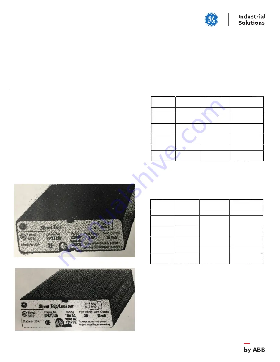
Figure 1. Shunt Trip.
Catalog
Voltage
Peak Inrush
Number
Rating (1)
Current, A (2)
Nominal RMS
Current, mA
SPST012
12 Vdc
3.0
200
SPST024
24 Vac
1.5
140
24 Vdc
SPST048
1.5
110
48
48
Vac
Vdc
SPST120
1.5
85
125
120 Vac
Vdc
SPST208
208 Vac
1.5
50
SPST240
1.5
40
250
240 Vac
Vdc
24-240 Vac devices are rated for 50/60 Hz.
Peak inrush current is present for 2-6 ms after activation.
This number is provided so that fuses and supplies can be chosen
appropriately.
Catalog
Voltage
Peak Inrush
Number
Rating (1)
Current, A (2)
Nominal RMS
Current, mA
SPSTL012
12 Vdc
19
300
SPSTL024
15
300
24
24
Vac
Vdc
SPSTL048
7.5
200
48
48
Vac
Vdc
SPSTL120
3.0
80
120
125
Vac
Vdc
SPSTL208
208 Vac
1.9
60
SPSTL240
1 .5
45
250
240 Vac
Vdc
1
GEH
6284
INSTRUCTIONS
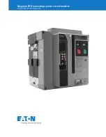
Power Break® II Circuit Breaker Accessories
Shunt Trip and Shunt Trip with Lockout
The catalog numbers for various voltage applications are
listed in Table 1 for the Shunt Trip and in Table 2 for the Shunt
Trip with Lockout.
—
Table 1. Catalog numbers and voltages for the Shunt Trip.
—
Figure 2. Shunt Trip with Lockout.
Introduction
The Shunt Trip and Shunt Trip with Lockout accessories,
shown in Figures 1 and 2, can be installed in 800-4000
ampere frame Power Break®II circuit breakers. These
accessories allow the breaker to be tripped electrically from a
remote location.
In addition to providing a trip signal to the breaker, the
Shunt Trip accessories can be set up to interact with other
Power Break II accessories, when used with a MicroVersaTrip
PlusTM or MicroVersaTrip PM™ Trip Unit. DIP switches on
the rear of the breaker Trip Unit can configure the Shunt Trip
accessories to activate a Bell Alarm-Alarm Only accessory or
a Bell Alarm with Lockout accessory when a shunt trip
occurs. The Accessory Configuration section below
describes how this can be done. If the breaker is equipped
with a Power+™ Trip Unit, it is configured so that only
protection trips will activate a Bell Alarm
Alarm Only or Bell
Alarm with Lockout.
—
Table 2 Catalog numbers and voltages for the Shunt Trip with Lockout.
Operation
Apply control voltage to terminals 31 and 32 of the terminal
strip on the right side of the breaker to trip the circuit
breaker. The Shunt Trip will cause the circuit breaker to trip
when the control voltage is greater than 75% of the rated de
voltage or 55% of the rated ac voltage. Control power to the
Shunt Trip must be removed before the breaker can be
closed. Control power to the Shunt Trip with Lockout must
be removed for a minimum of 0.25 second before the breaker
can be closed.
(1)
(2)