11.
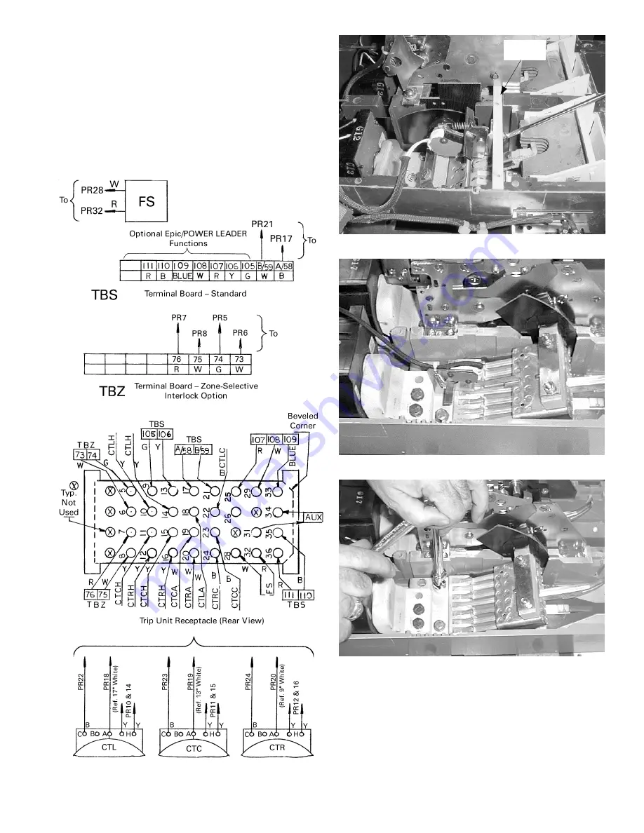
If an auxiliary switch is present, remove it as follows:
• 800–2000 A breaker, Figure 7: Remove the two
mounting screws.
• 2500–4000 A breaker, Figure 8: Remove the bolt,
lock washer, and flat washer securing it to the C
phase contact assembly.
If no auxiliary switch is present in a 2500–4000 A
breaker, remove and save the inner bolt, lock washer,
and flat washer on the C phase contact assembly, as
shown in Figure 9.
3
Figure 6. Wiring diagram for terminal board and trip unit plug.
Mounting
Bar
Figure 7. Old auxiliary switch in an 800–2000 A breaker.
Figure 8. Old auxiliary switch in a 2500–4000 A breaker.
Figure 9. Removing the inner bolt on the C phase contact assembly to
install the auxiliary switch in a 2500–4000 A breaker.


