12.
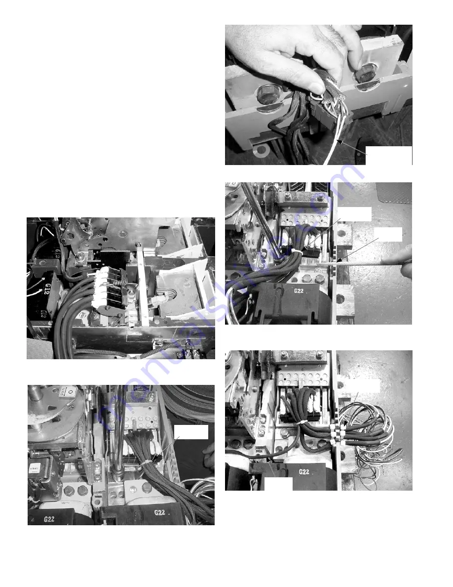
Install the new auxiliary switch [4] as follows:
• 800–2000 A breaker: Insert the new switch into the
breaker base and secure with the two screws [2]
supplied, as shown in Figure 10.
• 2500–4000 A breaker: Place the new switch over the
C phase contact assembly and secure with the bolt,
lock washer, and flat washer removed in the
previous step, as shown in Figure 11. Tighten the
bolt to 180–250 in.-lb.
In both cases, use small wire ties [5] to dress the wire
bundles.
13.
Insert the two white wires in the small auxiliary
switch cable into the trip unit plug in positions 31
and 34 (see the wiring diagram in Figure 6), as
shown in Figure 12.
4
14.
File three slots in the breaker base, as shown in
Figure 13, to accommodate the auxiliary switch wires.
15.
Run the five remaining auxiliary switch cables out
through the slots in the breaker base. Secure the
cables in position with large wire ties [6] for strain
relief, as shown in Figure 14.
Figure 10. New auxiliary switch [4] installed in an 800–2000 A
breaker.
Figure 11. New auxiliary switch [4] installed in a 2500–4000 A
breaker.
Figure 12. Auxiliary switch wires inserted into the trip unit plug.
Auxiliary Switch
Wires to Trip
Unit Plug
Figure 13. Filing slots in the breaker base for exit of the auxiliary
switch wires (2500–4000 A shown).
Figure 14. Auxiliary switch wires exiting the breaker (2500–4000 A
shown).
Wire Exit
Slots
Trip Unit
Wires
Large Wire
Tie [6]
Small Wire
Tie [5]
Small Wire
Tie [5]


