16.
Attach the new terminal board and bracket assembly
[1] to the breaker as follows:
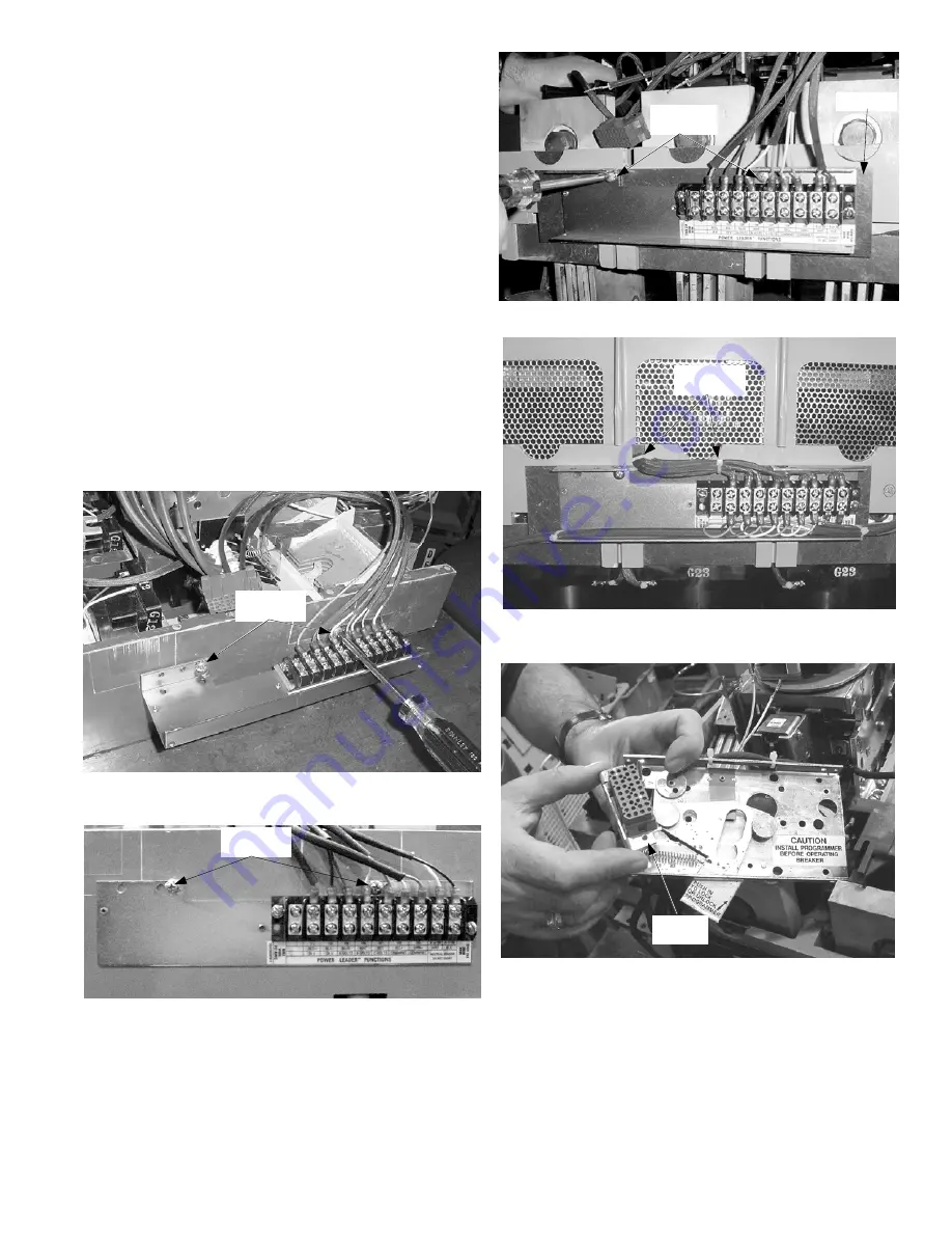
• 800–2000 A breaker: Secure the bracket with the
two #10-16 screws [2] supplied, as shown in Figure
15 for a stationary breaker and in Figure 16 for a
draw-out installation. File two additional slots in the
side of the breaker base for wires to pass through to
the terminal board.
• 2500–4000 A breaker: Install the bracket with the
two #10-16 screws [2] and barrier [3] supplied, as
shown in Figure 17.
5
17.
Connect the wires to the new terminal board
according to the wiring diagram in Figure 6.
18.
Arrange the wires neatly into the slot in the breaker
case, between the CTs, as shown in Figure 18. Use
small wire ties [5] as shown to dress the wire bundles.
19.
Slide the mounting bracket onto the large trip unit
plug and slide the bracket over the two pins on the
trip unit mounting plate, as shown in Figure 19.
20.
Use a thin screwdriver to bend the two locking tabs
on the trip unit mounting plate into the slots on the
plug bracket to hold the plug in position, as shown in
Figure 20.
Figure 15. New terminal board [1] installed on an 800–2000 A
stationary breaker.
Figure 16. New terminal board [1] installed on an 800–2000 A draw-
out breaker.
Barrier [3]
Mounting
Screws [2]
Figure 17. New terminal board [1] installed on a 2500–4000 A breaker.
Figure 18. Completed terminal board installation (shown with breaker
cover in place).
Figure 19. Reinstalling the large plug on the trip unit mounting plate.
Mounting
Screws [2]
Small Wire
Tie [5]
Plug
Bracket
Mounting
Screws [2]


