6
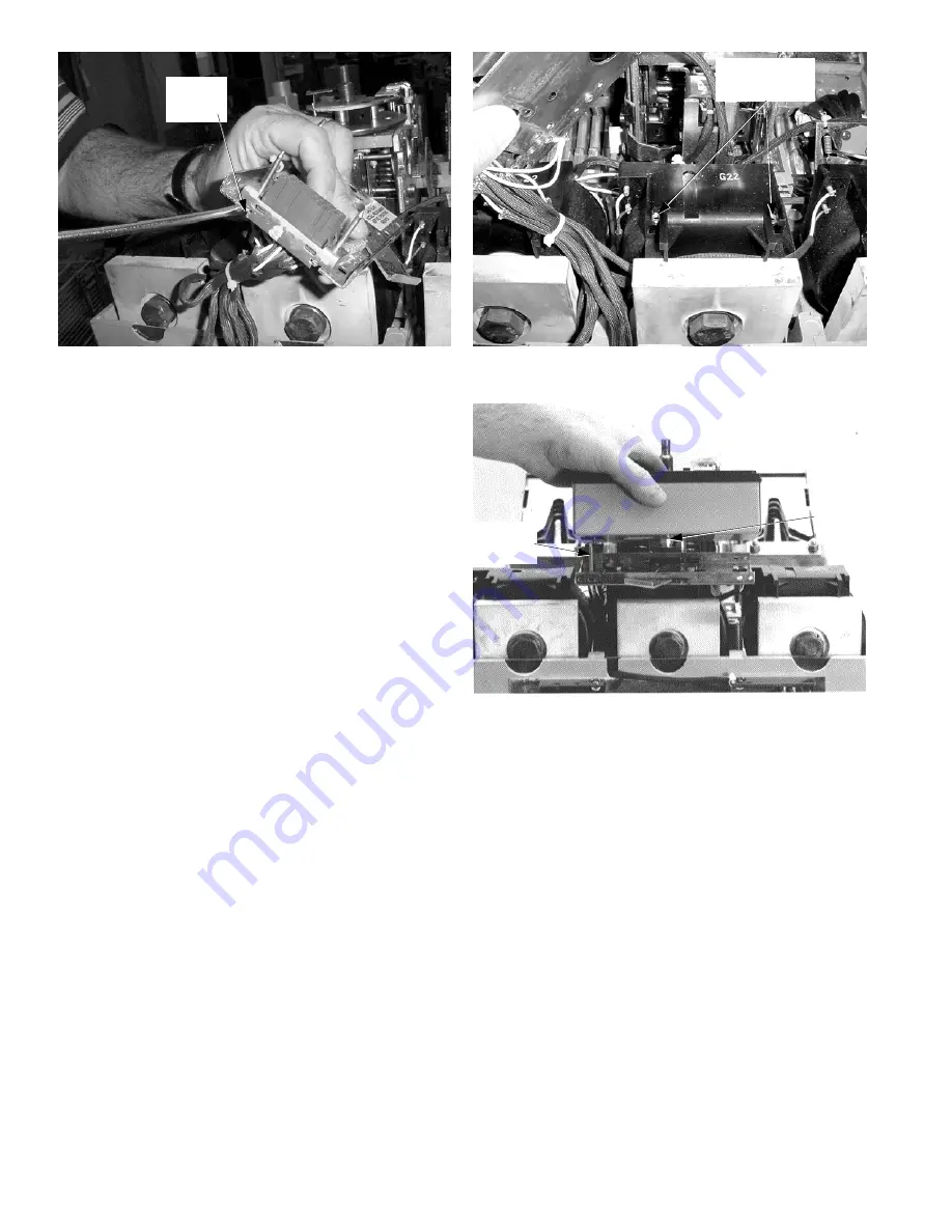
Figure 20. Bending the locking tabs to secure the trip unit plug to the
mounting plate.
21.
Attach the trip unit mounting plates to the breaker as
follows:
• 800–2000 A breaker: Slide the tab of the mounting
plate under the
1
/
4
-20 screw shown in Figure 2.
Insert the two mounting screws removed in step 8
into the holes in the plate and secure to the
mounting bar shown in Figure 7. Tighten all the
screws.
• 2500–4000 A breaker: Insert the two #8-32
x
3
/
8
screws removed in step 8 into the holes in the
mounting plate, as shown in Figure 3. Tighten the
screws into the nuts installed in the slots in the top
of the B phase CT, shown in Figure 21.
22.
Reinstall the trip unit as follows:
a.
Push in and hold the locking lever on the side of
the trip unit mounting plate.
b.
Carefully line up the guide pins on the mounting
plate with the holes in the rear of the trip unit, as
shown in Figure 22. Align the pins in the
connector on the rear of the trip unit with the plug
on the mounting plate. The alignment pin on the
rear of the trip unit must fit in the hole in the
locking lever.
b.
Push the trip unit against the mounting plate until
it is securely in position. Release the locking lever.
Draw-Out Breakers Only
23.
Install the new trip unit disconnect plug [8] on the
breaker side plate with the two thread-forming screws
[7] supplied, as shown in Figure 23. Run the wires
through the hole in the plate to the terminal board.
24.
Connect the wires from the breaker-mounted trip
unit disconnect [8] to the terminal board according
to the chart on the terminal board mounting bracket.
The pin arrangement of the trip unit disconnect
plug is shown in Figure 24. The wires from the trip
unit disconnect are grouped in sleeves as listed in
Table 5. If zone-select interlocking is not installed on
the breaker, those four wires (in two sleeves) may be
cut off or tucked out of the way.
Trip Unit
Mounting Plate
Screw Slots
Bend the
Locking
Tab
Figure 21. Trip unit mounting slots in the B phase CT on 2500–4000 A
breakers.
Figure 22. Installing the trip unit (800–2000 A breaker shown).
25.
Run the wires from the substructure-mounted trip
unit disconnect [9] through the slot in the side of the
substructure. Place the enlarged portions of the slots
in the disconnect slide over the two shoulder studs in
the side panel, as shown in Figure 26.
26.
Slide the trip unit disconnect forward in the slot,
then connect the spring [10] between the hole in the
slide and the anchor tab on the substructure, as
shown in Figure 26.
27.
Connect the wires from the substructure-mounted
trip unit disconnect [9] to the appropriate external
sources. The wire colors and groupings are the same
as those listed in Table 5. The pin arrangement of
the trip unit disconnect plug is shown in Figure 27.
Mounting
Plate
Guide Pin
Trip Unit
Alignment
Pin


