7
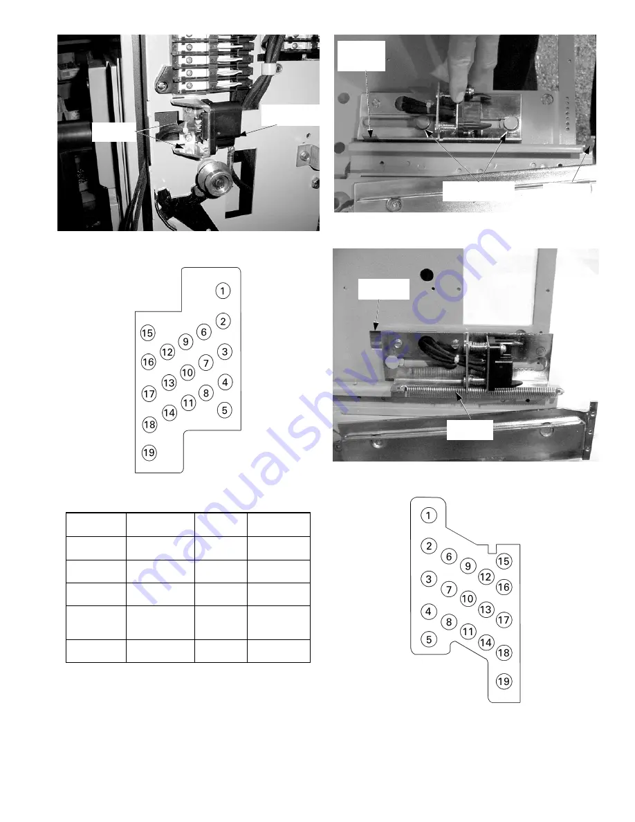
Figure 23. New trip unit disconnect [8] installed on the side plate of a
2500–4000 A breaker.
Figure 24. Pin layout of the breaker-mounted trip unit disconnect, as
seen from the rear.
Wire Color
Function
Sec. Disc.
Pin No.
Terminal
Board Point
green
white
zone-select
interlock
11
12
74
73
red
white
zone-select
interlock
13
14
76
75
green
yellow
power
management
2
6
105
106
red
white
blue
power
management
3
7
10
107
108
109
black
red
power
management
4
8
110
111
Table 5. Wire groupings from the trip unit disconnect.
Spring
Mounting
Hole
Figure 25. Placing the trip unit disconnect [9] on the mounting studs on
the substructure side panel.
Figure 26. Trip unit disconnect [9] installed on the draw-out
substructure.
Figure 27. Pin layout of the substructure-mounted trip unit disconnect,
as seen from the rear.
Trip Unit
Disconnect [8]
Disconnect
Mounting Studs
Mounting
Spring [10]
Wire Slot in
Side Panel
Spring
Anchor Tab
Mounting
Screws [7]


