– 22 –
Logic Board Replacement
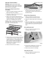
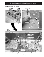
1. Remove the glass and cooktop from the
countertop (see procedure).
Sensor
Sensor
GEA00822
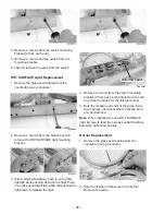
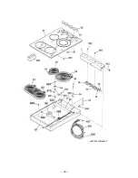
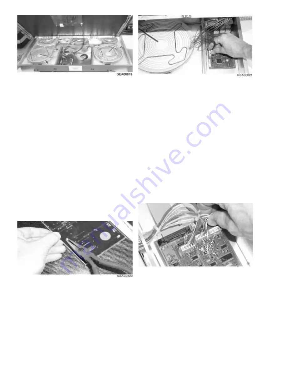
2. Disconnect the sensor connectors from the
logic board by pulling upward on the connec-
tors. Do
not disconnect the connectors by
pulling on the sensor wires.
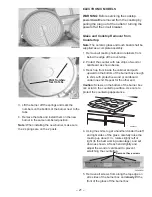
6. With the glass tilted at an angle, disconnect the
wire harness that extends from the logic board
to the user interface by pulling upward on the
connector. Do not pull on the wires.
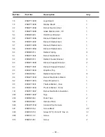
7. Remove the glass from the top of the burner
box and place top side down on a protected
surface.
Touch Board and Cooktop Glass
Replacement
Note: The ceramic glass and touch board shall be
supplied as a complete assembly. Remove and
replace the cooktop ceramic glass (see previous
procedure).
Display Board Replacement
1. Remove the display board from the damaged
piece of cooktop glass.
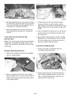
2. Place the display board on the new cooktop
glass, making sure to connect the 8-pin ribbon
cable to the touch board and the wire harness
to the display board.
3. Prop the glass on the back of the cooktop.
Using one hand to lower the glass, use the
other hand to connect the wire harness from the
display board to the 10-pin header on the logic
board.
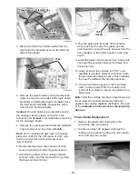
4. Lower the glass onto the burner box, being sure
not to pinch any wires between the frame and
the burner box.
5. Apply power to the cooktop. Once the cooktop
appears to be in working order, remove power
from the cooktop and insert all the screws to
secure the glass to the burner box.
Summary of Contents for Profile JP938
Page 19: ...17 Fault Code Behavior Table...
Page 33: ...31 Notes...
Page 34: ...32 Parts List...
Page 36: ...34...
Page 38: ......
Page 39: ......

